• Hi Guest!
    You can help ensure that British Car Forum (BCF) continues to provide a great place to engage in the British car hobby! If you find BCF a beneficial community, please consider supporting our efforts with a subscription.

    There are some perks with a member upgrade!
    **Upgrade Now**
    (PS: Subscribers don't see this gawd-aweful banner
Tips
Tips

Fuel Gauge - Sending Unit Question

gra

Member
Country flag
Offline
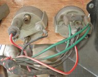
My BJ8 fuel gauge indicates about 5/8s of a tank when the key is on and just over 3/4s of a tank when the engine is running regardless of fuel level. Removing the T wire results in the gauge going to empty (I thought it was supposed to go to full) and grounding the T wire results in the gauge going to full (thought it was supposed to go to empty).

I have a new moss sending unit that reads 1.7 ohms to 100.2, which I understand from Moss is within their range of acceptability. From previous posts on this forum I understand the 100.2 may be on the high side but think the difference would result in inaccurate readings rather than static ones. I had the same gauge readings with the sending unit I just replaced.

The green wire is showing 12.2 volts. I believe the ground is good on the tank and on the gauge. I have used a separate lead wire to go direct from the fuel sender T to the gauge T with the same static gauge readings.

Any ideas would be greatly appreciated. Thanks George
 
I'd send the gauge to Nisonger to be serviced & calibrated. You've already replaced the sender, not much else left.
 
Sending to Nosinger is my next step after learning if anyone has any other ideas or tests that I might try first. Thanks George
 
I concur with Bob, I used the instructions on the MGA site and was able to ascertain that the gauge was identical to that shown on the site because there are lots of pictures. I then calibrated my gauge following the simple instructions and it has since been acurate and with no problems. The cost of the job was about an hours work and less then three dollars for resistors and wire.
The final calibration also allows for any residual resistances in the car's wiring loom etc and can be done regardless of the resistance range of the sender unit.
One small proviso, the sender when in the tank sometimes doesn't cover the same range of values as when measured out of the tank because of restrictions in arm movement within the tank. You really need to be sure what max and min resistance values at full and empty really are before you start. I'd advise measuring with a known empty tank and then with a known full tank before starting calibration. Not casting any aspersions on the work done by Nosinger but they have to assume that the sender moves through it's full range when in the tank. That may not actually be true.

Ian Irving
BJ8 Phase II
 
Wow, that is a great fuel gauge reference.

By the opposite than expected reaction observed when disconnecting the T and B, it is almost as if you have reversed the connections on the gauge.

With the T-connection removed and going to empty, it’s as if power to the gauge was removed. You mentioned the green wire has a 12.2V supply. Is this a single or double wire (should be 2 wires bound with a single connector)?

Here are a few Way-OUT questions. Have you checked to make sure the insulators on the T and B connections are in tact? Also, the only additional power at the gauge is delivered through the dash light. Have you checked to see if the disposition of the dash lights makes a difference in the gauge’s response?

All the best,
Ray (64BJ8P1)
 
Ian and Bob, thanks for the reference and the information.

Ray, I believe the T connection is the one on the left when looking at the back of the gauge. Does that sound right? The green wire is double with a single connector. The light being on or off or in or out of the gauge does not seem to make a difference.

I am not sure about the insulators on the connections. Is this inside the gauge or the wires themselves? I believe the wires are ok as using a separate lead on the T shows the same results.

Thanks George
 
If it helps, here's how mine is wired. The T terminal has the green/black wire. Hard to see in this photo.
 

Attachments

  • 22876.jpg
    22876.jpg
    71 KB · Views: 351
Hi George,

You are correct and as Randy’s pictures show, the double wire connector is nearest to the fender. As far as the insulators are concerned, the connectors on the gauge must be insulated from the case and, I believe, can be checked by disconnecting all connections a checked to discontinuity with a multimeter.

Bottom line, since the gauge is easily uninstalled, I would disconnect the ground wire and bracket and pull the unit clear of the dash to examine the back of the gauge. There is enough wire to keep the main connections in tact and you can then easily see if the dual wire is connected to the B terminal and the single wire is connected to the T. You can also see the insulators behind the connectors as well as the condition of the wires and connectors. You can also reconnect the ground and, with the key on, giggle the connections to see if there are any changes.

Although extremely improbable, when viewing Randy’s pictures, you will notice that the ground wire uses an exposed connector and can touch the power connection if that connection is exposed or damaged. Although I doubt that this is the case, as I believe the fuse would be blown.

George, I appreciate that you probably have done the things that I’ve mentioned but I thought I might as well give you my thoughts.

Randy, great pictures. How do you get the clarity in such close quarters?

Ray (64BJ8P1)
 
RAC68 said:
Hi George,

You are correct and as Randy’s pictures show, the double wire connector is nearest to the fender. As far as the insulators are concerned, the connectors on the gauge must be insulated from the case and, I believe, can be checked by disconnecting all connections a checked to discontinuity with a multimeter...

... Although extremely improbable, when viewing Randy’s pictures, you will notice that the ground wire uses an exposed connector and can touch the power connection if that connection is exposed or damaged. Although I doubt that this is the case, as I believe the fuse would be blown...

<span style="font-weight: bold">Randy, great pictures. How do you get the clarity in such close quarters?</span>

Ray (64BJ8P1)
:wink: Thanks, wait until you see this (high resolution image): https://www.rfdm.com/gallery/album209a/IMG_3678?full=1

Historically, all my documentation pictures (of cars I've worked on) have been 640 x 480 (pixel) size, but since I started using Watermark Factory 2 (batch) software, I've been doing them in 2048 x 1536 (pixel) size; or, REALLY BIG. Great if you're looking for a little detail that might be included in the image, while not being the main focus.

Currently, my <span style="font-style: italic">Sports Cars Plus, LLC</span> gallery is 140 primary albums (218 total, including all the embedded albums) and exceeds 19,015 separate pictures (remember that, if you suffer from insomnia...). There are a couple of paths to get there: www.rfdm.com/gallery or www.spcarsplus.com/gallery
 
Hi Randy
Who do you get the kits of bullet connectors, grommets etc from please and who sells the tool on the right of you crimping tools which I assume is for inserting the bullet connectors. I'd love to get the kits, there's nothing like starting with the right tools and parts.
Ian
 
IanIrving said:
Hi Randy
Who do you get the kits of bullet connectors, grommets etc from please and who sells the tool on the right of you crimping tools which I assume is for inserting the bullet connectors. I'd love to get the kits, there's nothing like starting with the right tools and parts.
Ian
I believe I got them from Holden, in the UK. I'll post some links up here later; I have to run out now to get a BMW 24 valve dohc cylinder head to the machinist__tight schedule this week...

IMG_3966.sized.jpg


Ian: don't be shy about reminding me...
 
You can get a bullet connector crimper (as well as connectors, grommets, wire, etc.) at British Wiring:

https://www.britishwiring.com/CAT28_29.PDF

Consider ordering the second tool on the page as it makes getting the connections right very easy. Or go to the home page, select 'Components' and check out the menu.

I've bought from them--very helpful and efficient.
 
British Car Specialists sell the correct bullets. I bought the solder on kind, but I believe they also stock crimp-ons. They also have the female connectors in single, double and triple configs.
 
Bob_Spidell said:
You can get a bullet connector crimper (as well as connectors, grommets, wire, etc.) at British Wiring:

https://www.britishwiring.com/CAT28_29.PDF

Consider ordering the second tool on the page as it makes getting the connections right very easy. Or go to the home page, select 'Components' and check out the menu.

I've bought from them--very helpful and efficient.
While on the subject of British Wiring, Josh sent me some pictures recently, and their concours harness (for the older cars, like 100/6s) is absolutely gorgeous!

I might have to get one of these for my car...
 

Attachments

  • 22888.jpg
    22888.jpg
    87.6 KB · Views: 245
The BJ8 sending unit provides around 90 ohms at full and close to zero (two or three ohms) at empty. That should be read at the green/black wire to the fuel gauge T terminal with respect to ground. This is different from the MG gauge described at the MGA Guru website, which reads about 68 ohms full.
It's possible to calibrate the Healey fuel gauge using the procedures at the website, but be very careful: loosen the small nuts on the adjusting studs ONLY enough to allow the studs to be slid in the slots with effort. If you loosen them too much, the locating "foot" on the coil (that fits in the adjusting slot, inside the case) can come out of the slot. If this happens, when you tighten the nut, the coil will spin and you will break the very small coil wire. The gauge will then not operate at all.
 
Back
Top