• Hey Guest!
    British Car Forum has been supporting enthusiasts for over 25 years by providing a great place to share our love for British cars. You can support our efforts by upgrading your membership for less than the dues of most car clubs. There are some perks with a member upgrade!

    **Upgrade Now**
    (PS: Upgraded members don't see this banner, nor will you see the Google ads that appear on the site.)
Tips
Tips

Front Suspension Tweak

Tosh

Jedi Trainee
Offline
Following changing to larger wheels 15x7 (0" offset) and tires 205/75/15, I encountered an interference problem between the upper ball joint to control arm mounting bolt heads and the inner wheel rim.

It appeared that on full lock turn, left or right, forward or reverse, the inner rim was contacting the nut or bolt head of the outer control arm to upper ball joint connection. The sound of the inner wheelweight snagged and sliding around the rim? Not encouraging!
Initially, I tried modified steering stops; two different sizes, larger than stock. This did not limit steering travel enough to prevent interference.
LimiterFromClipboard.jpg

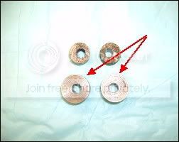
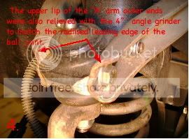
To deal with this this problem I removed both upper ball joints and control arms...

Then....
1FromClipboard.jpg
2FromClipboard.jpg


3FromClipboard.jpg
4FromClipboard.jpg


How does it work?

Clearance between the wheelrim and the front/rear of the ball joint on turn in is approximately 1/2 ā€œ. There is somewhat of a penalty on full turn in travel as the larger stops were left in place and adjusted to max limit therefore turning radius has increased. I notice this only when moving the car in my garage/driveway but the rims no longer contact the upper ā€˜A’ arm.
Note:
I am running reversed upper 'A' arm pivots and therefore more negative camber. I love the feel of this, however, I have the feeling that it may exacerbate the interference on turn in during full lock.

My suggestion? Save time and trouble by:

1. Not using 7 ā€œ wide wheels.

2. If using 7ā€ width wheels with 0ā€ offset try a 16ā€ wheel. The 1/2ā€ increase in diameter
would likely miss the bolt heads.

3. Using wheel spacer shim. I didn’t like this
alternative because of potential change in suspension geometry and (length of) wheel
stud issues.

A personal observation here. The stock front suspension is extremely flexible. There is a lot of force on the various components particularly during sharp turns. I have installed the GoodeParts suspension upgrade and it helps. I think that the TRF heavy duty front spindle kit is a necessity for these cars, even without larger wheels and tires. Of course, most of us already know about the reinforcing plates for the lower frame to 'A' arm brackets.


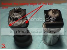
Also dimensions and, therefore, results may vary from ball joint to balljoint. As can be seen from the pictures the unmodified balljoint from TRF is made in Taiwan the modified one is from GB. There is a noticeable difference in mass between the two. This is not to say that the replacement is inferior.

P.S. With me, a project like this is never done.

Keep on, Merry Christmas.
 
It's great to see that someone is really thinking things out to solve a problem.

Have the a-arms been slotted for adjustment? The last photo (bottom right) looks like the nice grade 8 bolt has barely enough purchase under the head where it meets the arm. It looks inadequate to be strong enough. Maybe you could box the ends?

But otherwise, if it works for you, then good.

As Chris said, make it safe(r).
 
1sttr6 said:
That is an excellent color!

/bcforum/images/%%GRAEMLIN_URL%%/iagree.gif

The black bumpers are a sweet touch too... terrific looking car!
 
Thanks for the compliment 1sttr6. FYI the color is Platinum Metallic. A TR8 color.

Alright, Chris and PeterK you bring up excellent points and I have thought about each.

Here's what I concluded;

(For context; I have done ball joint replacement on my Ford Ranger. They are pressed and secured by a (maybe 1/8th") internal snap ring.)

1) Regarding the 5/16" dia. bolts (#5 grade as you observed).
a. they serve a locating as well as support function. Lateral pull (away or toward the the centerline would be easily controlled by the inner 3/8 " thru bolt.

2) According to my machinist (and his sometime assistant), a bolt need only penetrate depth equal to diameter to achieve max hold. That is to say a 5/16" bolt threaded 5/16" into an iron or steel object will break off at the head when significantly overtorqued. The depth of these front bolts @ .644" is almost twice that needed for max fastening power. My concern here was that by overtorqueing I would run the threads and ruin the ball joint.

3) The only possible failures I can envision with this setup are:
a. the front bolts loosen and drop out.
b. the front bolts shear.
As for (a), some red Loctite and they haven't moved a bit. Movement would be noticeable and audible if it occurred.
As for (b), [See discussion of tensile strength/shear strength by 'Billavista' and others]

https://www.pirate4x4.com/forum/archive/index.php/t-40342.html
and here
https://dodgeram.org/tech/specs/bolts/SAE_bolt_strength.html

No, the upper 'A' arm is not slotted but man! I am sure it can be done. A little machining on the balljoint housing surfaces, some welding and slotting on the 'A' arms. Wouldn't need much adjustment at all. I happen to have an extra set of 'A' arms and a welder and....well, another time maybe.

To wrap up. I realize this modification is not for every one. I performed this out of necessity. Either that or buy a different set of wheels. As it is I feel comfortable with it and short of track work, I don't think I'll have a problem.
(Track day at BeaverRun here in western PA precludes the use of soft top vehicles so that means run the Mustang or the BMW).

Actually I ruminate more about such things as those spindly TR steering columns and clamps and the rack itself and of course the 'A' arm to frame brackets oh! and the 4 bolt hub setup and the weenie front spindles and the flexible flyer chassis....

Thank you all for the discussion. What a great community.

Keep on.
 
I've done a little calculation what bolt size you might need.

With your 5/16 bolt you have a safty gap of about 23,9% - If you have a FULL bolt at the shear force point.
If you have the thread root at the shear force point of your construction then you don't have any safty left. A fast corner with a pot hole and your bolt might snap.
What it makes worse is that your bolt is at its maximum load step which causes early fatique failures - so after running the car several month or years the bolts WILL fail without any other cause.

Try to fit 3/8 bolts for safety reasons.

Cheers
Chris
 
Chris,

Shear force point?

Am not sure by what formula you base your conclusion. Seems that in order to arrive there you would have to know exactly what the loading forces are on the bolt. (Actually, it is 2 hex screws not a thru bolt)

To know that it would be necessary to account for a lot of unknowns and the interaction of various front end components including sprung and unsprung weight, inertia, speed, material composition, age of hardware, ad infinitum on the fastener. Yes?

Anyway Chris, duly noted and considered.

Keep on.

PS; Spent a couple of weeks in Würzburg in Oct. Love that country.
 
Notwithstanding risk, I must say I can see why you've
gone to the trouble. Very attractive look.
Thanks for sharing.

Can't leave without telling you that the last thing
I would like to have happen is to crash in my TR6.
I got this feeling like if it happens, results could
be categorized more than serious, and likely grave.

Like crashing driving a motorcycle. Guess it's the
old seat belts; no air bags....oh, and the fact I really
enjoy putting my foot into it has a lot to do with it.

Take care,
 
2wrench,

Yea, thanks for the compliment. Ya know our cars possess an aura and presence that is hard to define. They are beautiful but so primitive with regard to driver protection. Maybe that is part of the attraction.

Which reminds me of an event.

About 20 or more years ago a friend came upon a recent fatal accident involving a TR4. He was one of the first upon the scene. He also was a previous TR4A owner back in the day.
It was too late to offer aid to the deceased driver of the TR but my friend, and I cannot remember the details, related his attempt to put out a fire burning in the clothes of the corpse.
Apparently fuel had sprayed on the unfortunate soul and had ignited.
The thought of a serious accident in one of these buggies is sobering.

Keep on.
 
Absolutely, Tosh. Don't think the barbaric aspect
is the attraction for me; rather, I like the sound; the feel; the torque; the wind in my hair...the size can only
be described as fun... and the body lines are sexy.

Beyond that, it's just another convertible.
 
/bcforum/images/%%GRAEMLIN_URL%%/iagree.gif completely.
 
Tosh said:
Shear force point?

Am not sure by what formula you base your conclusion. Seems that in order to arrive there you would have to know exactly what the loading forces are on the bolt. (Actually, it is 2 hex screws not a thru bolt)

Maybe you can translate "ScherflƤchen" into English?
EDIT: found the word: "Shear planes"
You have 4 of them.

My calculation is very simpel and is concentrating on cornering forces.
 
Chris,
<div class="ubbcode-block"><div class="ubbcode-header">Quote:]Maybe you can translate "ScherflƤchen" into English? [/QUOTE]

You mean like "shear area of square measure"? That is as close as I can extrapolate from my German/English dictionary.

You say Chris that there are 4 of these. Why not for the sake of discussion say there are at least 12 per side and that is not counting the bolts on the spring pan or the shock absorber. I am assuming that wherever a bolt or screw passes thru steel and joins separate pieces of suspension you have shear force trying to cut through or pull the fastener apart.
<div class="ubbcode-block"><div class="ubbcode-header">Quote:]so after running the car several month or years the bolts WILL fail without any other cause. [/QUOTE]
The question I have is how does one conclude that a part will, unequivocally, fail at some point in time?

Keep on.
 
Several years ago I've worked at a material test institute. We tested how long metal parts resist coninously bending, pulling and other forces before it breaks off.

If a bolt is at its limit than I won't like to have it at my suspension parts or other safety stuff.

In the same way I broke a TR 4 rod. During the races the rod does operate at its limit and it does brake at the oil spill bore at the center of the beam part. Simple story. I upgraded the rods from shape and steel and now I can use up to 9000 rpm from the rod side. Now the crankshaft is the weak part and will break if I push it too far.

I still think your bolt is too small if you drive the car fast. For cruising it might be okay.

Happy new year Tosh. and all the others too.
 
wow MadMarx, we think so much alike! i am building my tr6 to drift. i ordered all poly front bushings (in the magic kit) the goodparts lowering springs, goodparts rear camber plates, rear coilover setup, nylatron trailing arm bushings, poly bushings for the diff, all new u joints, the 250 dollar trf competiton sway bars F&R, and the front koni shocks. i am not impressed with the non gas charged konis. what do you suggest? and how do i adj the konis (they dont have any directions or markings)a rollbar, all new wheel bearings, front axle upgrade kit, and the morgan rear wheel cyls. also doing 4 pot calipers and vented cressie rotors.
 
Back
Top