• Hi Guest!
    You can help ensure that British Car Forum (BCF) continues to provide a great place to engage in the British car hobby! If you find BCF a beneficial community, please consider supporting our efforts with a subscription.

    There are some perks with a member upgrade!
    **Upgrade Now**
    (PS: Subscribers don't see this gawd-aweful banner
Tips
Tips

TR2/3/3A dash light variable resistance tr3

sp53

Yoda
Country flag
Offline
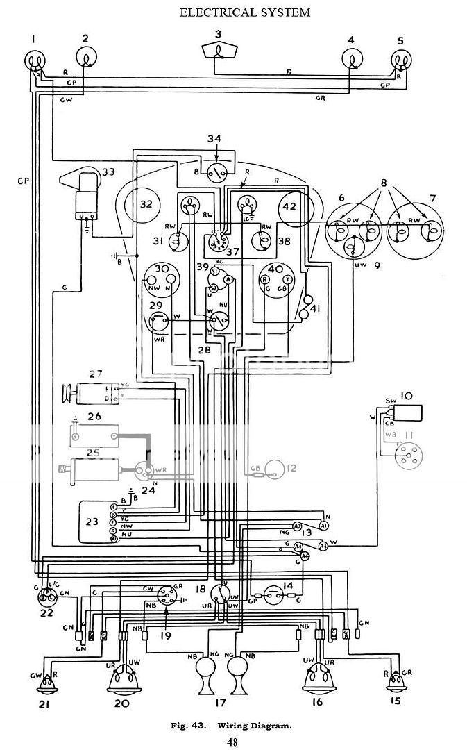
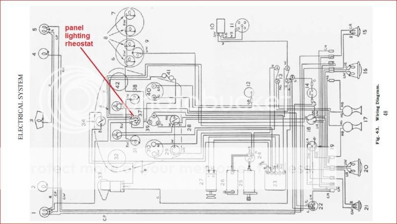
Hi all I have a question concerning how the wiring cascades through the dash light variable resistance switch on a 1961 tr3. In my case only one dash light comes on and it appears that the variable resistance does not work. Perhaps the switch only goes in one way, and I have it backwards, and if I switch the wires around that might fix the problem. The bulbs are all good and the tach cable is hooked up. I think they ground through the cables or at least that helps. Anyways, I guess I could convert to the older pull switch for the dash lights. Any suggestions on this are much appreciated.
Steve
 
Should not matter which way the rheostat (variable resistor) is connected. However, having one light come on would seem to indicate that either that one light is not wired to the resistor, or all the others are not connected somehow. I would pursue that avenue first.

The bulb holders are also kind of funky; if they get bent just a bit, the bulbs won't make contact. Sometimes, they work until inserted into the holder.

There is supposed to be a ground wire to the tach and speedo. It has ring terminals that go under one of the mounting screws for each instrument, and then as I recall goes to the ground tie point on the back of the instrument panel. The tie point in turn has a black wire through the harness that grounds near the control box under the hood. Grounding through the cables might work, but isn't a good idea IMO.

Your car should also have an in-line fuse clipped to the edge of the dash below the instrument panel. The fuse is mostly to protect the wire to the rear tail lights, but if it is bad, the dash lights won't work either.

TR3AschematicfromPracticalHints6the.jpg
 
Steve: This diagram is from the TR3A owner's manual. The red line indicates the variable resistor (rheostat) which controls the intensity of the panel lamps.
Hope it helps.
diagram-rheostat.jpg
 
Steve,
It's hard to see the difference in brightness, even in a total
dark environment. Turning the knob counterclockwise until it "clicks' will turn the dash lights off. Then turning it clockwise until it just clicks again will turn the lights on full bright, not utilizing the resistor. This setting should have all your lights on. If not & you're sure the bulbs are OK, it's almost certain a poor ground. They depend on the body of the facia and the bodies of the speedo & tach for ground.Try pulling the light sockets out one at a time and touching the case to the chassis. If the light(s) work, its a poor ground. I got tired of fooling with the speedo & tach lights and ran a separate ground wire to chassis ground. Changing to a push-pull switch poses a problem; The hole in the facia for a push-pull switch is smaller than the one for a resistor type and the flat side on the hole (to orient the switch properly) is on the opposite side.
Hope this helps.
Frank
 
Yes, Art that is the diagram that came with the wiring diagram from BW. When I look at the diagram, it looks to me like the dimmer switch has to different sides for hook up. I would just try and switch them to see what happens, but I have the heater in and besides I do respect Randall’s opinion. I was looking through some of my old wiring harness and found some interesting ground hookups that look like they would carry the ground continuously through the tach and speedo. I thought at first they were just something that somebody added and were perhaps not even for a tr3, but now I am not so sure. They look kinda like the large heater ground hookup, but they have two loops for grounding. Anybody ever see anything like that? I will try and get a picture out. Now that I have read Randall’s post a little better that must be what he is talking about. And yes it does really start to sound like a ground problem Frank and Randall, but I do not think I have that ground system on my pull switch 58 car.
Steve
 
sp53 said:
They look kinda like the large heater ground hookup, but they have two loops for grounding. Anybody ever see anything like that?
Yes, exactly. There was one on my 59 TR3A when it came to me, and one just like it on the 56 TR3 when it came to me.

Should be easy enough to fabricate if yours is missing.
 
Steve,
Randall& Frank A's diagrams are for the later 3A's with the rheostat,and like all schematics, show the electrical layout, not the physical layout. Can be quite confusing sometimes. The double eye wire you spoke of was intended to be attached to one of the (lower) wing nuts at the back of the facia and the other to one of the sheet metal screws holding the dashboard brace in place. On most harnesses there is another black wire that is to be attached to one side of the wiper switch. That wire is spliced to the double loop wire further back in the harness. The other end is attached to the E connector on the control box. To further add to the confusion, there were several minor electrical changes made during the production run that never made it to the wiring harness or the wiring diagrams.
I got so frustrated over the years that I made up my own diagram with all the little additions/deletions/changes that are particular to my 3A. What with CRS creeping up on me, I had to do something!
Frank C.
 
Well I put the ground wire loopie thingies on and the lights work as they should. One more for Randall, but who is keeping score besides (me). Anyways thanks all for your fine input.
steve
 
Back
Top