• Hi Guest!
    You can help ensure that British Car Forum (BCF) continues to provide a great place to engage in the British car hobby! If you find BCF a beneficial community, please consider supporting our efforts with a subscription.

    There are some perks with a member upgrade!
    **Upgrade Now**
    (PS: Subscribers don't see this gawd-aweful banner
Tips
Tips

TR2/3/3A Confirming Cam Set Up

jruddsr

Freshman Member
Country flag
Offline
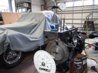
I need some help. I am rebuilding my Tr3 engine and have installed a new standard camshaft, chain and gears. The WSM is pretty clear about timing the cam with unmarked gears. Set cam at point of balance on cylinder #4. Set #1 piston at TDC and install chain. My cylinder head is not installed so I made a “Macy’s Garage” dial indicator setup and degree wheel.
This is pretty straightforward, if this is correct.
Now for my problem. The WSM provides a nice graphic of the crank rotation with intake and exhaust valve timing. Intake opens at 17 degrees BTDC and closes at 57 degrees ABDC. Exhaust valve specs are also provided. Try as I might, I cannot confirm those specs with my degree wheel. What am I missing?
 

Attachments

  • C4C17B0C-059E-4FBC-BAA9-0ACA80C94BD6.jpg
    C4C17B0C-059E-4FBC-BAA9-0ACA80C94BD6.jpg
    69.5 KB · Views: 148
Timing using cam lift is a bit more complicated than just reading the lift. Some list the valve opening as initial cam movement, .030" of lift, or .050" of lift. This is because the initial ramp on the cam is very subtle as the lash in the valve train is being taken up, and then motion is faster and easier to measure.

So, my first question is if the cam came with a degree card that tells at what cam lift they measure the timing? It should be something like: .012" or .050", etc.
 
Point of balance on #4 ....doesnt look like you are checking #4 ... 2 push rods in #4 will have a zeropoint where one is the same height as the other
with the 1 pistol at TDC, you will be as close as a stock cam has to be .NOT up to race spec however and you will not have checked to see if the
specs on the cam are accurate.This can come as quite a shock but I have seen badly cut cams.....
MD(mad dog)
 
John, There was no degree card included with the standard cam. I guess the idea is, since it’s a standard cam, use the WSM method and don’t worry! (Be happy).
MD, I set the point of balance at #4, installed chain with #1 at TDC. I moved the dial indicator to #1 in an attempt to confirm the cam was set up correctly. I was hoping I could confirm the specs in the manual, but no luck. I think you are saying use the WSM method and move on, right?

John
 
OK...I think I understand...you set up the balance point at #4, just as you should. But if the crank is at that point in the rotation, you would have to check the lift on #4 intake for 15 degrees before TDC movement.

In other words, the #1 cylinder is in the firing stroke where you set the cam, so the #1 valves are both closed tightly, and will be for almost 1/2 crank rotation. To do your check, assuming you have just set the cam sprockets, and you are now set up on the #1 tappets, you will need to move the dial indicator to the intake tappet, which is the second lifter from the front of the block. Then turn the crankshaft clockwise from the front for 345 degrees...to 15 degrees before the NEXT TDC, but almost one full rotation out from where you set the cam in the manual instructions. This point is where the second lifter should start to move upward.
 
Last edited:
The basic idea is that you set the crank at TDC and the cams for that cylinder to the point where the valves are open the same amount; then that is TDC at the exhaust cycle. You can do this with any cylinder. Then install the timing chain, with the camshaft timing gear in the position that makes the chain fit precisely. Frankly, I thought that the method in the shop manual was not likely to be very accurate. Here is what I did:

http://tr4a.nonlintec.com/engine/#timing

The engine is finished and the car is on the road. It runs very well.
 
Back
Top