'59 Bugeye. Dual horn set-up. No relay, Moss says I don't need it. I've wired the two horns in series. (pigtails across the terminals) I now have two.wires off one horn that are looking for connections. My loom has a brown/green tracer and brown and black tracer. Do I connect my horn wires to these tracers and how do they match up? Brown and green goes to the fuse block, brown and black to the horn button which I don't have yet. This is all guess work. Please check my work.

-
 Hey Guest!
British Car Forum has been supporting enthusiasts for over 25 years by providing a great place to share our love for British cars. You can support our efforts by upgrading your membership for less than the dues of most car clubs. There are some perks with a member upgrade!**Upgrade Now**
(PS: Upgraded members don't see this banner, nor will you see the Google ads that appear on the site.)
You are using an out of date browser. It may not display this or other websites correctly.
You should upgrade or use an alternative browser.
You should upgrade or use an alternative browser.
Bugeye dual horns
- Thread starter rossco
- Start date
Bill Young
Senior Member
Offline
assuming the horns are rated 12 vdc ... wire them in parallel

Offline
If you have 2 wires from one horn then I think you have them parallel. If you have wires between the horns then there should be 2 wires between them. The diagram shows 2 separate wires from the relay, one to each horn then both grounded. The NG wire is the hot wire to the relay and the the NB wire is the relay coil and goes to the horn button. There should be a NY wire from the relay to each of the horns and a B wire from the horns to ground. If you are not using a relay then the NG wire would got directly to the horn or connect to the NY wire. As you adjust to the Lucas way of doing things, the color codes are as follows.
N = brown
B = black
Y = yellow
R = red
G = green
W = white
U = blue
P = purple
K = pink
Wires with a tracer color have gone through a switch (mostly) other than the ignition switch. Solid color wires have not, again except possibly the main ignition switch. You really need that diagram.
N = brown
B = black
Y = yellow
R = red
G = green
W = white
U = blue
P = purple
K = pink
Wires with a tracer color have gone through a switch (mostly) other than the ignition switch. Solid color wires have not, again except possibly the main ignition switch. You really need that diagram.
I have two diagrams. I've never used one and I'm trying to find my way along. Hooked both wires from the horns to test battery, got sound. Reversed the wires and got sound. Checked for continuity on NB horn push wire - o.k. Checked for continuity on NB wire to fuse B - o.k. Now can I join the two wires from the horns to the two loom wires and hook up a manual horn button because a don't have a horn button on the steering wheel.
Bill Young
Senior Member
Offline
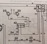
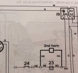
Here is a schematic that shows how the factory wired a single horn or the optional dual horn setup.
#19 is the fuse block. #23 on the bottom of the drawing is a single horn and #24 is the horn button. At the top of the drawing the two #23's are the dual horns, #42 is the horn relay, and #24 is the horn button.
#19 is the fuse block. #23 on the bottom of the drawing is a single horn and #24 is the horn button. At the top of the drawing the two #23's are the dual horns, #42 is the horn relay, and #24 is the horn button.
Attachments
Offline
I think I made a misleading or at lease incomplete statement above about wiring around the relay. The NG wire from the fuse box goes to one of the horn wires. The other horn wire goes to your horn switch. With a standard horn button this wire is NB somewhere in the wiring harness. Since you are adding a separate button, you probably will have to supply a separate wire from the horn to the button. The other side of that button then must be grounded.
Offline
Relays are fairly logical and not hard to wire. All relays have standard markings as per the diagram, you would run the existing horn wires from the battery to 86 to 87 to the horn (which grounds when you push it)What relay do you use and do you just install it in line? I've never done a relay.
this creates a small electromagnet which is wired: new line from battery (mine comes from the solenoid) to 30 - and then from 87 to the horns which are grounded as per the diagram. any relay you buy from anywhere will be marked 85/86 - and 30/87. Some even come with harnesses.
Ignore 87a in the diagram this is an extra terminal for something like a high/low headlight beam.
good luck!
Offline
I get that!JP. Thank you! I'll look at this fresh in the A.M. when I have a fresh head. I'm up too late for an oldguy.R
BTW I have two relays and two wires - one on each horn
Offline
I have a square body Midget. IIRC the horn ones are behind the grill on the horn brackets and then I have three more on the drivers side mounted on the inner fender near the front - They are out of sight and are for low beams high beams and a spot light.Where are they mounted?