Hi Guest!

 Hey - did you know if you click on the title of a thread it will take you to the first unread post since you last visited that thread?
 but were afraid to ask:
  STOP!! Never post your email address in open forums. Bots can "harvest" your email! If you must share your email use a Private Message or use the
  smilie in place of the real @
 Pretty Please - add it to our Events forum(s) and add to the calendar! >>
Hello.
I'm back with a new question regarding electrics on my 100/4.
Everything seems to work properly, but the 35A fuse blows when driving, without any obvious cause - switching anything on, for example...
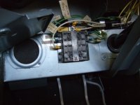
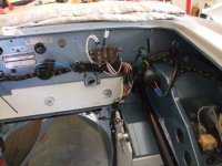
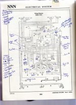
Therefore, in order to find the culprit and after a wiring diagram check, I decided to add a slightly smaller fuse on every 4 green wires protected by the 35A one. Unfortunately, when I look at the car, there are... FIVE green wires connected to the 35A !
Does anybody know where the fifth one is coming from ?
Additionnally, except plugging / unplugging each wire in turn, is there an easy way to identify their function ?
Thank you in advance for your advices.
Matt
I'm back with a new question regarding electrics on my 100/4.
Everything seems to work properly, but the 35A fuse blows when driving, without any obvious cause - switching anything on, for example...
Therefore, in order to find the culprit and after a wiring diagram check, I decided to add a slightly smaller fuse on every 4 green wires protected by the 35A one. Unfortunately, when I look at the car, there are... FIVE green wires connected to the 35A !
Does anybody know where the fifth one is coming from ?
Additionnally, except plugging / unplugging each wire in turn, is there an easy way to identify their function ?
Thank you in advance for your advices.
Matt