Hi Guest!

 Hey - did you know if you click on the title of a thread it will take you to the first unread post since you last visited that thread?
 but were afraid to ask:
  STOP!! Never post your email address in open forums. Bots can "harvest" your email! If you must share your email use a Private Message or use the
  smilie in place of the real @
 Pretty Please - add it to our Events forum(s) and add to the calendar! >>
Bill Young
Senior Member
Offline
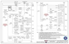
It has never been easy to figure out how all the electrical components actually work using the "point to point" connection diagrams we have in our manuals. As a life long controls engineer (retired), I decided to see if I could create a usable "ladder logic" diagram presenting the functional logic of the electrical system. The attached diagram was developed for the 3000 MK III late BJ8. It is a 11 X 17 tabloid size. I have contacted Reid, our AHCA Chatter editor (and forum moderator) about publishing this diagram and future diagrams for the other Healey models in the Chatter. He suggested that I have a peer review of this diagram and see what the members of the forum think. I am open to corrections, suggestions, and comments as appropriate, to make this a resource for our Healey service and maintenance work. Being new to the forum, I found out that the file is to large to attach in the .pdf format, but it will attach in the .jpg format. I am not sure how this will work... so I an sending. Let me know if you would like a .pdf of this drawing.. Looking forward to your input .... Bill Young. sjahc.com