• Hi Guest!
    You can help ensure that British Car Forum (BCF) continues to provide a great place to engage in the British car hobby! If you find BCF a beneficial community, please consider supporting our efforts with a subscription.

    There are some perks with a member upgrade!
    **Upgrade Now**
    (PS: Subscribers don't see this gawd-aweful banner
Tips
Tips

TR6 Auxiliary Circuit Sanity Check

PGSberg

Freshman Member
Offline
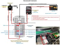
1975 TR6. I am contemplating installing a auxiliary circuit so not to tax the existing aging wiring. I’ve read, read and read, and think I have a winter project plan. I’d like a sanity check from you experts out there before I set my car on fire. LOL. I’m pretty sure some of the OEM wiring may have been replaced with other colored wire therefore I’d rather not mess with what is working until I learn more and sort that out.

For planning, my attached diagram has more accessories than I would need.

1 - I'm not installing a killer stereo with amps and speakers mounted on the trunk or off road lights. Best AWG for the main electric/ground? Best to Ground to battery or to the Battery Ground on the Firewall?
2 - Proper AMP Relay for the Switched Circuit?
3 - Proper AMP for Circuit Breaker?
4 - Haven't looked under the dash so hope the ACC blade is well marked on the ignition switch or is there a better location in the engine compartment?

I’m not an auto electrician by any means. Thanks for constructive feedback.
 

Attachments

  • MASTER Aux Circuit 20 Jul 2024.jpg
    MASTER Aux Circuit 20 Jul 2024.jpg
    176.6 KB · Views: 54
IMHO every late Tr6 is a fire waiting to happen. It is imperative that the brown wires that
attach to the positive cable be run through a fuse block. I have seen too many dash fires.
The idea of running multiple un-fused wires into a metal dash is bonkers and dangerous.
Once you have the fuse block installed, wire away in such fashion as you like, secure in the
knowledge the car is much safer than the day it was new.
Mad dog
 
I looked over your diagram pretty carefully, and I think it all looks pretty good. I might make a couple suggestions:

1. The wire sizes are largely intelligently selected. I've always used #16 for circuits with moderate current requirements and #14 a few places with greater current demand. I don't think you need to go to #12 for anything. #8 for the battery run is fine.

2. I always run the battery ground directly to the engine block. I retain the usual engine ground strap to the frame and make a connection from the battery, frame, or engine block to the body. I think that grounding the battery to the body, as the factory did, is a mistake. The battery to engine block (or body) connection should be the usual thick cable, as it has to carry ~125A starter current. The wire to your new fuse block can be #8.

3. You might consider relays for lights or any other high-current circuits. It will extend the life of the switches.

4. While the use of the 80A breaker is prudent, it has one disadvantage: it takes 80 amps to trip it. If something shorts downstream, it may fry the wiring but not trip that breaker. So, that breaker really protects only for a few possible disasters between the battery and the block. After that, everything should be fused, but of course that is what you are doing. In my cars, everything is fused.

5. I wonder about a couple of your current estimates. A USB charger (presumably with a lighter socket) should require 15A only if you use the lighter socket for a real cigar lighter. The one you get probably will not be usable for that, anyway; it's intended just to plug in a GPS or something like that. Also the radio constant-on connection is very low current, much less than an amp.

I have rewired four cars in a similar manner. My MGTD was a complete rewiring job, as the wiring, when I received the car, was a nightmare. In my TR4A, I largely retained the existing wiring harness, replacing parts of the harness that needed it and liberally adding relays and fuses. Here's my story:

> Body electrics <

Here's my MGTD story, which might be useful as a case study:

> Body Electrical Restoration <

Just so you know--I'm an electrical engineer with multiple degrees and 50+ years experience. So, I'm not a complete babe in the woods with this stuff.
 
Last edited:
I looked over your diagram pretty carefully, and I think it all looks pretty good. I might make a couple suggestions:

1. The wire sizes are largely intelligently selected. I've always used #16 for circuits with moderate current requirements and #14 a few places with greater current demand. I don't think you need to go to #12 for anything. #8 for the battery run is fine.

2. I always run the battery ground directly to the engine block. I retain the usual engine ground strap to the frame and make a connection from the battery, frame, or engine block to the body. I think that grounding the battery to the body, as the factory did, is a mistake. The battery to engine block (or body) connection should be the usual thick cable, as it has to carry ~125A starter current. The wire to your new fuse block can be #8.

3. You might consider relays for lights or any other high-current circuits. It will extend the life of the switches.

4. While the use of the 80A breaker is prudent, it has one disadvantage: it takes 80 amps to trip it. If something shorts downstream, it may fry the wiring but not trip that breaker. So, that breaker really protects only for a few possible disasters between the battery and the block. After that, everything should be fused, but of course that is what you are doing. In my cars, everything is fused.

5. I wonder about a couple of your current estimates. A USB charger (presumably with a lighter socket) should require 15A only if you use the lighter socket for a real cigar lighter. The one you get probably will not be usable for that, anyway; it's intended just to plug in a GPS or something like that. Also the radio constant-on connection is very low current, much less than an amp.

I have rewired four cars in a similar manner. My MGTD was a complete rewiring job, as the wiring, when I received the car, was a nightmare. In my TR4A, I largely retained the existing wiring harness, replacing parts of the harness that needed it and liberally adding relays and fuses. Here's my story:

> Body electrics <

Here's my MGTD story, which might be useful as a case study:

> Body Electrical Restoration <

Just so you know--I'm an electrical engineer with multiple degrees and 50+ years experience. So, I'm not a complete babe in the woods with this stuff.
Thanks so much for taking your expertise and time to look over. I'll definitely recheck and rethink a couple things. I figured some of my estimates on the accessories was a bit high.
 
Back
Top