• Hi Guest!
    If you appreciate British Car Forum and our 25 years of supporting British car enthusiasts with technical and anicdotal information, collected from our thousands of great members, please support us with a low-cost subscription. You can become a supporting member for less than the dues of most car clubs.

    There are some perks with a member upgrade!
    **Upgrade Now**
    (PS: Subscribers don't see this gawd-aweful banner
Tips
Tips

Alternator wireing

MadMarx

Jedi Warrior
Country flag
Offline
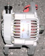
I have installed an new alternator as an upgrade from a Lucas alternator.

The Lucas one had only 2 connections....big and small....

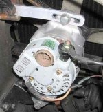
The new one has 4 connectors: A big one and 3 small ones....

None of them make my ign. warning light burn....

They are named as: D, IG, L...

I could imagine that D is ground and L is light?

Anyone who has an idea?

Cheers
Chris
 

Attachments

  • 5575-DSCN2074.JPG
    5575-DSCN2074.JPG
    14 KB · Views: 786
The "L" terminal is for the dash idiot light.
The "IG" terminal goes to the Ignition. It must be supplied with current when you turn on the ignition.
The "D" terminal...well, on Japanese alternators, the "D" stands for, believe it or not, dummy. It doesn't do anything. On Bosch alternators, it has a different meaning.
 
Well, looking at the picture, I'd say that is a Nippondenso or Hitachi unit. It doesn't look like a Bosch. Are you sure you're not refering to who rebuilt it?? Bosch rebuilds all units, whether they be Japanese, European or American. They will label them according to how the OEM did it, not to how they do it on their alternators.
 
when i put a gm 105 amp alternator on my tr7 i purchased a pigtail to jumper a couple of connections together to get it to work properly. don't quite remember the connection identification though.
 
MM- I use to have the info on the Bosch but can't seem to find it. Hopefully someone else might have it. I thought it was a straight swap and connection. I think I'm with Art, Not a Bosch
 
As BOSCH is my sponsor they send me that alternator. It is a replacement for a Nippon-Denso type.

The codes on the Nippon Denso are different:
B/A, E, F, L, IG/R

The Bosch:
B+, D-, DF/DFM, D+/61/L

As there are no E or F on that alternator I assume the D on the alternator could be D-?
 

Attachments

  • 5581-DSCN1783a.jpg
    5581-DSCN1783a.jpg
    53.5 KB · Views: 806
Send it back and have them send the right (correct) one Fiesta
 
MadMarx said:
As BOSCH is my sponsor they send me that alternator. It is a replacement for a Nippon-Denso type.

The codes on the Nippon Denso are different:
B/A, E, F, L, IG/R

The Bosch:
B+, D-, DF/DFM, D+/61/L

As there are no E or F on that alternator I assume the D on the alternator could be D-?

OK, forget all of that nonsense. What you need to know is how to make this alternator work. My contention is that "IG" is an ignition feed. That "L" is the light circuit, and that "D" is dummy. Do not hook anything to "dummy". Hook up the other wires. The fat wire to the output stud, the "L" to the lamp circuit, and the "IG" to a switched ignition source. Start the car, put a volt meter on the battery, and let us know how it's going.
 
I agree with Art.

At least you'll get a charge or no charge point to move forward from, after doing what he suggests.
 
I have a four-wire Denso installed on the Elva.

Three terminals are in a molded modular plug/pigtail and the prongs are from left to right:

1. The "IGN" terminal (green wire on the pigtail) which connects to the ignition switch and energizes the alternator.

2. The "S" terminal (blue wire on the pigtail) which connects to a 12 V distribution post and senses system (as opposed to battery) voltage.

3. The "L" terminal (red wire on the pigtail) which grounds a charge warning lamp.

The large "B" terminal on the alternator body is the output terminal and goes to the battery.

You can hook up "S" and "IGN" to any switched source of 12 volts and "L" is optional, but for a good explanation of the advantages of a four-wire alternator system over a one-wire go to:

https://www.smcccd.cc.ca.us/smcccd/faculty/sullivan
 
Michael Oritt said:
1. The "IGN" terminal (green wire on the pigtail) which connects to the ignition switch and energizes the alternator.
2. The "S" terminal (blue wire on the pigtail) which connects to a 12 V distribution post and senses system (as opposed to battery) voltage.
3. The "L" terminal (red wire on the pigtail) which grounds a charge warning lamp.
You can hook up "S" and "IGN" to any switched source of 12 volts and "L" is optional, but for a good explanation of the advantages of a four-wire alternator system over a one-wire go to:
https://www.smcccd.cc.ca.us/smcccd/faculty/sullivan

Thank you Michael,

So you have an S terminal and I have a D terminal. Seems that they do the same.
My thin wire is the warning lamp. The lamp is connected to switched + and it has to be ground to make it light.
If I connect this line to IG and S (D) then it should work?

The upper link doesn't work....

My engine is not full installed so I can't fire it up at the moment....
I'd like to start up to make that red light flash first when I turn the IG key.

Cheers
Chris
 
Chris:

You said:

"So you have an S terminal and I have a D terminal. Seems that they do the same. My thin wire is the warning lamp. The lamp is connected to switched + and it has to be ground to make it light. If I connect this line to IG and S (D) then it should work?"

My understanding of the purpose behind putting in a sensing circuit is so that the internal regulator will charge the battery according to actual system voltage as opposed to voltage at the battery, which is the only source of voltage feedback with a one-wire system. This allows for voltage drop and spikes, etc. You can tie the "IGN" and "SENSING" wires together--you just lose the above feature which is not really critical.

The warning lamp must connect to a terminal on the alternator that provides a ground when the alternator is not putting out current--it will not work if connected to the above wires.
 
Mad Marx--

There should be some current passing in the "IGN" circuit to energize the alternator. Most important, is there current out of the alternator to the battery? Your system voltage with engine running should be about 13.5 VDC--if not the alternator is not putting out properly.

BTW the only reason I used a four-wire Denso alternator in the Elva is because I was able to buy it for peanuts and it was lighter than the MG generator. If this unit is going in a race car (as shown on your avatar) I would recommend that the next time around you use a one-wire alt. The current-sensing is really pretty irrelevant for racing installations and as you know lots of folks don't even run alternators/generators in race cars. I just wired the sensing wire to the ignition wire and left the "lite" wire disconnected.
 
Back
Top