• Hi Guest!
    You can help ensure that British Car Forum (BCF) continues to provide a great place to engage in the British car hobby! If you find BCF a beneficial community, please consider supporting our efforts with a subscription.

    There are some perks with a member upgrade!
    **Upgrade Now**
    (PS: Subscribers don't see this gawd-aweful banner
Tips
Tips

Transmission Heat Deflector and Seal Photo Needed

AUSMHLY

Yoda
Country flag
Offline
Hello all,

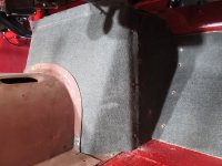
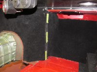
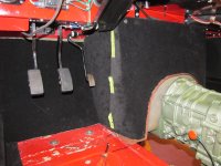
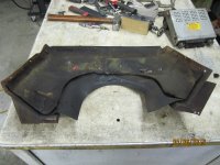
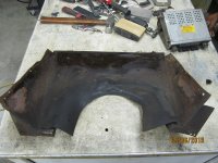
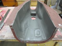
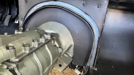
Does anyone have any photos of the original Transmission Heat Deflector and Seal installed on the BN1-BN7 cars?

British Cars Specialist sells one, but not sure if it's the original material or not.

The material is not as important for me as is a photo showing the original in the car.

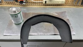
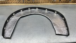
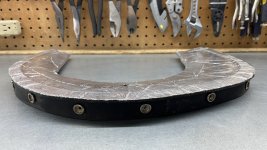
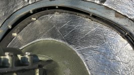
I'm making a seal for my BJ8 and would like to show the original for the BN1-BN7 series and the comparison of what I'm making and how to install it in the BJ7-BJ8.

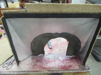
I'll include a photo (from BCS drawing) of the two pieces, metal deflector and the seal for reference.

Thank you in advance.

4833F1EA-3BA2-4E23-965D-1AA1BD798BA2.jpg
 
I bought one for a center shift transmission (BT7 MkII). It is flat, horse shoe shape. The outside edge rests on the firewall lip that the gearbox cover pilots on. There are some flanges extending from the outside edge that are bent 90 degrees to attach the deflector to the firewall lip. The inside edge follows the bell housing. There is a circular cutout for the starter pinion cover and a half circle cutout for the overdrive harness. A rubber hose is sliced lengthwise to make a seal between the deflector and the bell housing.

The fellow I bought it from is no longer with us. I'll see if anyone in his club has any available.
 
Thanks Bob for your info. I'm just looking for a photo. I'm not incorporating those two pieces (metal deflector/rubber seal) into my BJ8. I'm making my own design that will fit the BJ7 and BJ8. I will share my design when finished.
 
Thanks Bob for your info. I'm just looking for a photo. I'm not incorporating those two pieces (metal deflector/rubber seal) into my BJ8. I'm making my own design that will fit the BJ7 and BJ8. I will share my design when finished.
The BJ7/8 design would be the same as the BN7/BT7 MkII fitted with a center shift gearbox. I'll see about getting some photos this weekend.

I did get a reply to my email to the club - he said that he had some overheating issues after fitting it to his BT7 tri-carb and isn't sure it's worth pursuing. It would be interesting to know why the factory didn't seal the gearbox tunnel with the center shift gearbox like they had for the side shift. Was there a technical reason or just financial?
 
I also wonder if the engine compartment temps go up - if you are preventing the hot air from going over the tranny, in effect does that make it harder for the hot air to escape the engine bay???
I've never had a center shift car so only dealt with the side shift type tranny cover. Here are some pictures of mine - seems like with the fiberglass cover, you would just need to add a flange in the fiberglass to attach a heavy rubber skirt to at about the tranny/bellhousing junction. The original material is sheet metal with about 1/16"-1/8" thick rubber sheet (a little heavier than an inner tube) attached with 6-8 split rivets and mine had heavy asphalt felt covering on the engine side of the metal, with jute and carpet on the cockpit side.
 

Attachments

  • IMG_8246.JPG
    IMG_8246.JPG
    639.9 KB · Views: 91
  • IMG_8250.JPG
    IMG_8250.JPG
    749.1 KB · Views: 87
  • IMG_8290.JPG
    IMG_8290.JPG
    523.8 KB · Views: 80
  • IMG_8293.JPG
    IMG_8293.JPG
    585 KB · Views: 82
Bob, Red57, Thank you for joining me on this ride. I appreciate the photos Bob!

Bob..."mine had heavy asphalt felt covering on the engine side of the metal". Is that the silver material?

It looks like the thermal reflective barrier I'm using. > Radiant Shield™ - Reinforced Foil Heat Shield <

Did it make a difference in cooling the transmission or heating up the engine bay?

I too have concerns about the engine compartment heat rising being I'm blocking one escape path to the transmission cover.
Why didn't they incorporate the heat shield in the BJ7/8 ?
It serves a purpose in the earlier Healey's.

Well, I'll find out when I install mine.
As they say, this design looks good on paper.
 
Last edited:
Red57, How many screws attach the metal frame?
Does it need to be removed when removing the transmission or access to the bleeder on the top of the slave cylinder?
 
Clarifications:
The first picture I posted earlier (8246) shows > Thermo-Tec Automotive < Cool-It, modern thermal barrier I installed where the heavy felt was. I don't know how effective it is in this application but I had some scraps left over from other projects, so I used it rather than felt, and jute and carpet on the outer surface. I glued 1/4" thick closed cell foam heat/sound insultation to the underside of the tranny cover and, again jute & carpet on top. I stay very cool & comfortable in the car.

My cars are a BN4 and a BT7 and always had this trans cover system so don't know the effect it has on heat transfer compared to the later fiberglass cover w/out the thermal barrier.

The 2nd picture I sent earlier shows the attaching screws - three on each side horizontally going towards the bellhousing that I believe are OEM and two on the top outer corners going horizontally forward into the heater cross tube. I am not sure the 2 at the top are OEM, my holes were stripped out from repeated removal and installation over the years so I had to install RivNuts and am using machine screws. There are also some vertical screws going down into the top of the frame tube holding the long tranny cover as well as the corners of this vertical panel.

I have a remote bleeder so don't need to remove anything for that, but the panel does need to be removed to access/remove the transmission.

First picture shows heavy asphalt felt (can't be sure the asphalt felt is original - could be a PO effort) and 2nd picture shows w/out felt (you can see some of the screw holes). Last picture is the closed cell foam.
 

Attachments

  • IMG_1926.JPG
    IMG_1926.JPG
    2.6 MB · Views: 69
  • IMG_1927.JPG
    IMG_1927.JPG
    2.6 MB · Views: 71
  • IMG_8269.JPG
    IMG_8269.JPG
    579.3 KB · Views: 72
Last edited:
Here are some poor photos of the heat shield fitted to our BT7-tricarb. In the first two images you can see a grommet on the OD harness that should be attached to the shield.

042A3033.jpg
042A3035.jpg
042A3042.jpg


There are five tabs on the outside edge that are bent over and screwed into the firewall flange.
 
Thank you Bob.
Is the silver... sheet metal with a rubber trim on the bottom edge and around the starter metal cap?
Is that black duct tape at the outside edge?

Red57 photos look different from yours.

042A3033.jpg
 
Last edited:
Red57
The back of the metal frame looks like it has two materials?
The bottom one looks like rubber that touches the bell housing and on top of that is that tar paper? Was this factory applied?

This photo looks like a different set up from your other photo? Both photo below.
IMG_8246.JPG

IMG_1926.JPG
 
Last edited:
As I said, the black asphalt felt may or may not be OEM (could be a PO effort). The rubber is definitely OEM & attached directly to the metal with 6 or 7 split rivets and washers (like a shorter version of the rivets used on the bonnet buffers). The picture with the aluminum is the way I recovered it because I didn't happen to have any heavy asphalt felt, but had the Cool-It. So I glued the foil backed insulation on to the metal first and then riveted the rubber on - same effect.
 
Last edited:
Thank you Bob.
Is the silver... sheet metal with a rubber trim on the bottom edge and around the starter metal cap?
Is that black duct tape at the outside edge?

Red57 photos look different from yours.

View attachment 101195
aluminum duct tape sealed the outside edge of the deflector to the firewall/gearbox cover flange. The dull silver in the middle is the deflector - flat piece of stainless steel sheet, I believe. On the inside edge, some rubber tubing slit lengthwise to rest against the gearbox and the starter pinion cover.

Red57's is the factory design for the side shift gearbox. I've been told mine is a Malcolm Terry design for the center shift gearbox.
 
Thank you Bob for explaining how yours was created. Now I see what I thought was black duct tape is really aluminum tape.
The cut out for the starter pinion cover help keep the stainless steel sheet in place which is nice.
Does the bottom of the metal shield with the split rubber tubing touch the perimeter of the bell housing making a tight seal?
When you need to remove the transmission, I'll assume you remove/replace the aluminum tape?
Simple and thought out design.

Have you noticed any difference in heat reduction in the transmission cover area thereby reducing heat felt on the cover or in the cabin?
Have you noticed any difference in increased heat in the engine compartment? Anything affected like the carburetors over heating or affecting performance? Hope not.

A lot of questions, so thank you for your replies. I'm sure others who might want to do this are also interested in having one of these. I'm making a tutorial video of how to make and install one. I'll post it on YouTube and share the link here when I'm done.

Cheers,
Roger
 
Bob besides the foil tape, did you said there are five tabs on the outside edge that are bent over and screwed into the firewall flange.
Attached by 5 screws and foil tape as seal around the edges. Brilliant.
 
Here's my design for the center shift transmissions heat deflector. (5 pictures. May take a little time to upload) Later I’ll post a Youtube video with the step by step.

The black material is 1/8” MLV, Mass Loaded Vinyl. It's a sound blocking material, which will address the exhaust and engine noise.
The silver material applied to both sides of the MLV is a heat shield material. The foil temperature rating is up to 1000 degrees.

Even thought the Radiant Shield is self adhesive, that glue will eventually come off the MLV material. MLV is very selective about bonding products. HH-66 Vinyl Contact Cement works great, so I applied that to the MLV and radiant shield. > HH-66 Vinyl Contact Cement <

The deflector makes a good seal around the bell housing and the metal top lip. There's a 1/8" MLV lip extending off the back of the shield to stop the air/heat from going between the metal lip and the MLV where it's snapped. 2nd and 4th picture.

Thanks to Bob and Red57 who helped me by providing photos for this project.
Cheers, Roger

IMG_2445.JPG
IMG_2446.JPG
IMG_2447.JPG
IMG_2450.JPG
IMG_2453.JPG
 
Last edited:
Seems the prior photos don't always upload.
Maybe this will work.
 

Attachments

  • IMG_2439.JPG
    IMG_2439.JPG
    3.5 MB · Views: 46
  • IMG_2440.JPG
    IMG_2440.JPG
    3.6 MB · Views: 46
  • IMG_2445.JPG
    IMG_2445.JPG
    3.6 MB · Views: 47
  • IMG_2447.JPG
    IMG_2447.JPG
    2.1 MB · Views: 49
  • IMG_2451.JPG
    IMG_2451.JPG
    3.2 MB · Views: 50
  • IMG_2452.JPG
    IMG_2452.JPG
    3.9 MB · Views: 57
FWIW ... OK... late to the party... and maybe nobody cares at this point.... but I'm kinda in Red57 camp regarding engine/transmission heat buildup.... at least that's how I read his comments. That was my concern ... and it is why I choose to allow the heat/air to continue to move out of the engine compartment and over the transmission. I used aluminum panels spaced 1/4" off the tunnel to direct air and isolated the transmission tunnel. I then added insulation on the outside of the tunnel (HushMat Ultra) to further isolate the heat from the interior. I did this on my last build and current build and have been satisfied with the results.

Of course, none of this meets originality issues if that's your goal.

But, as I said, I'm very happy with the results... tunnel stays cool and, seemingly, I don't add to the buildup of heat in the engine/transmission.

Cheers... Happy New Year!
 

Attachments

  • IMG_7427 S50.jpg
    IMG_7427 S50.jpg
    1.4 MB · Views: 52
  • AH heat shield Small 4080 043.jpg
    AH heat shield Small 4080 043.jpg
    56.7 KB · Views: 47
  • 6 - HushMat Ultra installed on tunnel S50 7468.jpg
    6 - HushMat Ultra installed on tunnel S50 7468.jpg
    1.5 MB · Views: 53
Back
Top