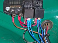
I did it and I'm very happy with the results. I don't have good pictures of the overall wiring but I will share what I have and try to explain. For reference I'm in North America and my car is Left Hand Drive, so if this doesn't match your situation it may be confusing.
1. The fuse box.
The top slot in my fuse box was empty so I used it. The original headlight circuit is second from the bottom. The brown wire on the left is power (from the alternator/battery) and the purple harness on the right runs through the dash switches and feeds the headlights. I jumped the brown wire (3rd row left) to the empty slot (top row left), added a fuse, and then ran two wires from the fuse to the relays (top row right).
2. The relays.
There are two relays, one for the high beam and one for the low beam. Each relay controls both sides. I mounted the relays on the front of the wheel arch, behind the left headlight, because it was easy. Each relay has four wires: power (from the fuse box), switched output (to the lights) and trigger (from the switches inside the car), and ground.
The power is a straight line along the edge of the hood from the fuse box. The ground wire is connected to any convenient spot. The trigger and output wires are connected into the existing wiring harness.
3. The existing harness.
The headlight wiring harness is accessible by removing the driver-side radiator shroud. There are two three-way connections you will need to locate. One for the high beams and one for the low beams. Both connections are located on the left side of the car. Each is a clip that accepts four bullet plugs (two at each end). The three wires for each connection are source power, output to the left light, and output to the right light.
It's important to note that the bullet connectors in these cars are bigger than the modern North American standard. If I use the modern male bullet connectors in the old female clip the result is a loose fit that will fail. If I try to crimp the old female connector it will shatter. The best solution is to source the correct bullet connectors that match the original wiring harness. The exist and can be ordered off the internet. Highly recommended. You will need four male bullet connectors plus two female/female bullet adapters. Basically each connection you pull apart results in one male side and one female side. Your new wires will need the matching ends.
Here is a diagram of the wiring harness (for a 76) with the junctions highlighted in yellow. Note that on some cars the output wires from the connector are on the same end (with the source at the other end) and in other cars this isn't true. You should trace and identify (and label) all six wires before you start.
4. Finishing up.
For the high-beam circuit you disconnect the source wire from the connector and replace it with the switched output from your relay. The original source wire now becomes the input/trigger wire for your relay. Repeat for the low beam circuit, test, and then replace the radiator shroud panel.
For me that's really all there was to the project. It would have been trivial but I mis-identified a couple of wires and didn't know about the bullet connector size mis-match until after I started. So mistakes were made

(but corrected later).
It was an easy job, the results are wonderful, and the whole thing can be reversed because no wires were cut.
Best of luck!

 Hi Guest!

 smilie in place of the real @
 Pretty Please - add it to our Events forum(s) and add to the calendar! >>
