• The Roadster Factory Recovery Fund - Friends, as you may have heard, The Roadster Factory, a respected British Car Parts business in PA, suffered a total loss in a fire on Christmas Day. Read about it, discuss or ask questions >> HERE. The Triumph Register of America is sponsoring a fund raiser to help TRF get back on their feet. If you can help, vist >> their GoFundMe page.
  • Hey there Guest!
    If you enjoy BCF and find our forum a useful resource, if you appreciate not having ads pop up all over the place and you want to ensure we can stay online - Please consider supporting with an "optional" low-cost annual subscription.
    **Upgrade Now**
    (PS: Subscribers don't see this UGLY banner)
Tips
Tips

Rough Running 99 XJ8 after Overheating

Michael J.

Jedi Warrior
Offline
In my other post I mention my experience with a failed Thermostat Housing on my 99 XJ8 4.0 V-8. After replacing the thermostat housing and the water pump, car was running rough with a number of codes.

One thread on the subject of overheating said that you can experience valve seats coming loose and or possible head gasket leaks.

I don't see evidence of any coolant on the engine oil dipstick.

I ran a compression test.Left front cold was 125 psi, All others read between 190 and 200 psi. I pulled fuse #7 in the trunk fuse box so that the fuel pump would not operate. I turned over the engine while listening for some out of ordinary sound, but did not hear anything different than the other cylinders.

I want to check the torque for the head bolts. Anyone able to provide the torquing pattern and the torque value? Is there something else that I should check?
 

DrEntropy

Great Pumpkin
Platinum
Country flag
Offline
I'd suggest a leak-down test, Michael.
 
OP
M

Michael J.

Jedi Warrior
Offline
I ran a leak down test that indicated that I had a serious problem.

I ended up buying a replacement 4.0 jag v-8. I won't mention the source.

First off, Jaguar decided to have three different versions of the normally aspirated 4.0. All three use the same block and intermediate deck that provides the bottom half of the crank supports. But there are different cast aluminum lower oil pan assemblies (3 according to the XJ8 & XJR Supplementary Information 1998 - 2002 DVD from Jag Heritage) and at least two timing chain covers.

Two different oil pumps. I am getting a low oil pressure light at idle, but this is not by biggest problem.

What I was expecting after just over $3,000 for the engine, core charge residential shipping, tommy lift fee and base shipping was an engine configured for my car, ready to drop in and connect the accessories.

A cautionary tale; make yourself very clear about which model jag you have i.e. XJ8, XK8 or S-Type or you will not necessarilly get the correct set up and have to swap the oil pan and timing covers.

The engine that arrived was not for an XJ8. I had to swap oil pan and timing cover to be able to mount the various componants. The engine as delivered uses an oil cooler and a remote oil filter. My XJ8 does not.
 
OP
M

Michael J.

Jedi Warrior
Offline
I have two OBD codes.
PO336- Crankshaft Position Sensor Circuit A Range/Performance. Where is this sensor located? There is one sensor at the bottom of the engine that reads a timing wheel on the frontside of the ring gear flexplate. A Bank is the r/h cylinder bank. One sensor reads at the timing gear at the front of each valve cover. When you pull the valve cover that sensor stays bolted to the head. A second sensor is at the rear of each head on the inside and reads valve timing from the rear of one of the camshafts.

Any ideas which sensor the code is talking about and how do you test it?

The second code is P1648-Knock Sensor Input Chip. Knock sensors are inside the V between second and third cylinder on each side. On my engine and the engine that arrived the sensor is mounted on a stud securred with a nut. I assume that it reads vibration? Sensor resembles a 1/2" thick washer with a cable that connects on each side of the thermostat tower at the front of the engine.

I assume that the input chip is mounted in the computor? How do you test this?

Engine runs not quite smooth and still wants to overheat. Checked plugs and all are firing.

HELP!!!
 

jessebogan

Jedi Knight
Offline
I will try this again. I had a whole post disappear... The crank sensor is the one on the bottom of the engine that reads the flywheel Was the hole for the sensor in the same place on both engines? If not, did you change the flywheels too? Can the flywheel be installed more than one way? IE "clocked" differently on the crankshaft? I need answers to these things.. The "sensors" on the front of the VCs are the actuators for the variable valve timing units. The ones in the rear should be cam position sensors, probably not relevant to this. I am guessing the knock sensor code is pointing to a bad sensor. Recheck your connections, (crank sensor too), and if nothing improves, replace the offending sensor. I don't have a diagram handy for a car of your vintage, so it is a little tough.
 
OP
M

Michael J.

Jedi Warrior
Offline
The rear face of the crankshaft flange has a single dowel in addition to the bolts. However, there is a hole where a pin could have been installed 180 degrees opposite.

Because the XJ8 oilpan is different than S-type or XK-8, I had to swap oil pan and casting to the new engine from the one removed.

You bring up an interesting point in that it is possible that pin on new engine crank was 180 degrees off from the position on the original.

I had to transfer the flex plate to the new engine. It may be that gap to the timing ring on the flex plate is different. I can check two things, put a dial indicator and check variation in gap if the flex plate is warped in some way. I can measure the depth between the face that the sensor bolts to to the face of the timing ring. What is the gap between the sensor and the timing ring face supposed to be?
 
OP
M

Michael J.

Jedi Warrior
Offline
It has rained here just about every evening for the last couple of weeks.

I finally was able to check things out this morning. I could not get a dial indicator set up to measure fore and aft flywheet play. There is no room with the steering rack right there. I tried through the rectangular rubber access at the bottom of the bell housing connecting the magnetic base to the suspension cross member, but I could not keep the dial indicator probe in the right place along the side of the ring gear.

So I was not able to determine if the flywheel is warped allowing the gap to fluxuate front to back for the crank sensor probe. So, I will have to look at how to get that reading.

The DVD manual did not indicate anything about the placement being significant regarding the alignment pin, at least that I saw. Is there an alignment arrow or other mark to coincide with the dowel pin? It will only fit two ways if the flex plate has a second dowel pin hole, but since the crank has two locations that the pin could have been installed, Before I pull the tranny to get at the flex plate mounting bolts, I would like to know more about how to verify the placement. You do have to have the timing ring facing forward for the sensor to read the ring. When assembling the flexplate onto the engine, I did not try wrong face forward so I can't tell you if it could be installed backwards.

I was able to obtain another ECM with the exact same part number, but the car won't start with it.

My friend had a problem this week with his 98 XJ8 in which his car suddenly would not start. However, It would start with his spare key. He thinks the key has a chip imbedded and the chip failed. If there is a chip, how is the box and key programmed to read each other? That might be why the car won't start with the "new" ECM.
 
OP
M

Michael J.

Jedi Warrior
Offline
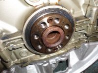
Attached is a photo of the crankshaft flange for the engine removed showing the single dowl and the 180 degree opposite hole that dowel could be installed in. The illustration in the Jaguar XJ8 & XJR Supplementary Information CD shows only one dowel alignment hole on the flex plate. So the flywheel can only mount in two positions 180 degrees apart.

Section on Valve timing indicates the variable valve timing adjusts 30 degrees max. So, I don't think Flex plate is 180 degrees off, it would be too great to allow engine to run. How can you check ignition timing or if variable valve timing is working correctly? The valve timing uses the solenoids at the front of each valve cover to control oil pressure to the valve timing piston It may be that the valve timing is not correct. How do you diagnose the variable valve timing?
 

Attachments

  • 28869.jpg
    28869.jpg
    65.2 KB · Views: 342
D

Deleted member 8987

Guest
Guest
Offline
I don't know as variable timing will give you no start.
Does the vehicle have the basics, compression, fuel and spark?
While together, did you connect a timing light to #1 (rear) and see if it flashed the timing pointer?

At this point, with it apart, harder to test anything, but, put a wrench on the front damper bolt, rotate with plugs out of the forward 5, rotate in normal direction with rear plug in, until you feel it start to come up on compression.
Stop.
Pull the plug, visually (or with a welding rod) continue rotating until it's roughly at the top of the stroke, then see where the sensor is in relation to the trigger on the flywheel.
If they line up (or close), the flywheel, I would guess, is correct, if the ignition needs #1 sensed to fire correctly.
Dave
 

jessebogan

Jedi Knight
Offline
My question was this. Was the alloy plate that the crank sensor attaches to exactly the same on both engines? And was the flywheel exactly the same? The crank sensor reads the (triangular I think) holes in the "face" of the flywheel. If the hole where the crank sensor attaches is in a different place, or the flywheel holes are different in relation to #1 cylinder, then the computer will get a very wrong signal, and should substitute a value so the car runs, but it will set a code. How many flywheels do they list for the V8? The valve timing stuff is pretty reliable. Sometimes the variators will rattle on start up due to oil leaking past the solonoid o rings, but they are usually OK. If you crank the engine around until the "timing stop dowel" fits in the flywheel (It will only fit one hole on the flywheel), remove the valve covers and see if you can fit the timing tools to the cams. If they all line up, cam timing should be OK. (Note, it could be 1 full turn off, ie none of the flats would be up, if so, remove dowl, rotate engine 1 full turn, and re check.
 
OP
M

Michael J.

Jedi Warrior
Offline
I had to swap the alloy plate from my old engine to the new engine. The Rebuilt Engine was configured for either a XK8 or an S-Type, whichever has a remote oil filter mounting whereas my XJ8 has the oil filter attach at the lower right front.

So the sensor mounted in the same place because I had to use the lower casting and oil pan. I also used the same flywheel Rebuilt engine came with a bare flange.

I will have to order the cam shaft tool. The tool for the V-12 and XK inline six has a different radius.

There are no V-8 engine parts listed on the Jag Hertage CD manual and no procedures at all on maintenance. Only general discussions.

The timing ring that the sensor reads us spot welded to the front face of the flexplate.

I will see what I can find.
 
OP
M

Michael J.

Jedi Warrior
Offline
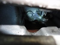
The photo below shows the flywheel sensor removed and the lock pin partially inserted in the hole. It was hard to photograph because it is right behind the steering rack. There are square holes spaced around the timing ring, but only one oval hole there the pin will insert lockingg the flywheel at what appears to be top dead center for number 1?
 

Attachments

  • 29018.jpg
    29018.jpg
    37.6 KB · Views: 305
OP
M

Michael J.

Jedi Warrior
Offline
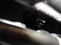
This photo shows the locking pin inserted all the way engaging the oval hole. The pin will not insert into the square holes.
 

Attachments

  • 29019.jpg
    29019.jpg
    22.4 KB · Views: 305
OP
M

Michael J.

Jedi Warrior
Offline
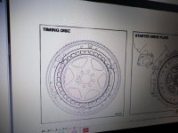
This is a poto from my computer screen showing the timing disk spot welded to the front of the starter flywheel.

You can see the square holes and the one oval hole. You can also see the dowel pin hole that aligns the position of the flywheel onto the crankshaft flange.

With the flywheel positioned and locked in place with the pin through the sensor hole the flats on the camshafts are supposed to be both on top and aligned flat.
 

Attachments

  • 29020.jpg
    29020.jpg
    46 KB · Views: 303
OP
M

Michael J.

Jedi Warrior
Offline
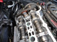
This is a photo of the left cylinder bank. Intake cam on the right and exhaust on the left. While the exhaust cam alignment flat is level with the top of the head, the intake appears to be about a half tooth off.

I read an article on Jag Lovers.org that said that the short chain connecting intake and exhaust cams is held on to the exhaust cam with friction only and not with the type of toothed adjustment we are familiar with on the XK and V-12 engines.

<span style="font-weight: bold">What is the torque for the bolt securing the gear to the front of the exhaust cam?</span>
 

Attachments

  • 29021.jpg
    29021.jpg
    63.8 KB · Views: 308
OP
M

Michael J.

Jedi Warrior
Offline
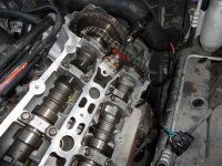
This photo is the right hand bank. Intake cam on the left and exhaust cam on the right. Intake is clearly off a tooth.

So I think I found my problem.
 

Attachments

  • 29022.jpg
    29022.jpg
    62.2 KB · Views: 298
OP
M

Michael J.

Jedi Warrior
Offline
So, which cylinder location is supposed to be at top dead center when the locking pin installed in the crankshaft sensor is in place?

I re-read the Jag-Lovers timing chain article again and found that the torque for the cam sprocket allen head bolts is 70 ft/lbs or 94 Nm.

More to come.
 
OP
M

Michael J.

Jedi Warrior
Offline
With regard to the dowel position on the crankshaft flange, To get an idea of whether the dowel was in the correct location on the new engine or 180 degrees off, I aligned the cam flats on the engine I removed and then looked at the position of the dowel and then looked at the diagram a few posts earlier that showed the timing disk on the flywheel.

The dowel is aligned with the sensor hole that the lock pin is inserted through and that corresponds with the illustration.

I also determined that the front r/h cylinder is at top dead center when the lock pin is installed.

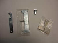
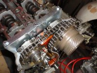
For those not familiar with the bar that locks the cams in position for the v-8 engine see the photo below.
 

Attachments

  • 29029.jpg
    29029.jpg
    60.3 KB · Views: 294
Similar threads
Thread starter Title Forum Replies Date
C Rough-Running 3000 Austin Healey 29
tr6web TR6 TR6 rough running - what can it be? Triumph 17
BierRunner TR6 TR6 Running Rough Triumph 5
T TR2/3/3A rough running after 20 min shutdown Triumph 9
J Spitfire 1979 Spitfire Running rough [sputtering, exhaust poping] at start up Triumph 2
N Stuck Needle Valve - Rough Running Austin Healey 15
glemon TR5/TR250 Stumped TR250 Running Rough--Follow Up Triumph 3
glemon TR5/TR250 Stumped TR250 Running Rough Triumph 8
D Rough running BT7 3 carb HELP Austin Healey 13
B Thoughts...rough running at cruise. Austin Healey 3
GTP1960 TR2/3/3A Rough running / a lot of carbon on the plugs Triumph 11
K TR2/3/3A Dead Petronix and rough running..... Triumph 10
I BJ8 is running a bit rough. . . Austin Healey 7
B Pics of my ’63 BJ7 and Questions on Hard Starting and Rough Running Austin Healey 11
bigbadbluetr6 TR6 TR6 carb question and running rough Triumph 13
T TR2/3/3A TR3 Running Rough - Cause[s]? Triumph 8
K TR2/3/3A TR3 Running Rough Again? Triumph 7
bighealeysource BN6 runs rough on restart after running great Austin Healey 7
M 87 Series III XJ6 Rough Running Jaguar 16
G Rough running and backfiring MG 30
M TR2/3/3A Another rough running TR3 Triumph 1
T TR2/3/3A TR3 running rough Triumph 6
vping Running rough MG 9
bighealeysource Up-date on engine running rough on my BN6 Austin Healey 1
A rough running after long idle or long low rpm driv Triumph 1
R TR2/3/3A TR3 Missing [running rough not stolen!] Triumph 4
tahoe healey surging and rough running Austin Healey 20
K TR2/3/3A TR3 Running rough..Cam or Carbs?How to diagnose? Triumph 10
H MGB-GT Help with my 1967 MGB GT running very rough MG 5
R TR6 Rough running TR6 = Pertronix? Triumph 27
Woodie rough running Spridgets 7
S TR2/3/3A Rough Running TR3A - help with diagnosis Triumph 11
A TR4/4A TR4A running rough question[s] Triumph 11
Woodie missing, running rough etc etc Spridgets 25
J running rough / missing Spridgets 7
77MidgetMkIV Rough running at weird intervals-any thoughts? Spridgets 22
77MidgetMkIV Now running really rough-help?!?! Spridgets 15
beebopbogo Engine running really rough - 2 cyls? MG 8
D TR6 Gp 2 cam, head shaved ,shorter pushrods, with a rough idle Triumph 10
P Spitfire 1979 Triumph Spitfire starts then runs rough Triumph 2
K TR2/3/3A Mystery clunking and banging from rear of car when driving over rough road or bumps? Triumph 14
H TR4/4A 67 tr4a runs rough and losses power when hot but not over normal temp Triumph 14
skystryd remind me it's fun. good idle. rough when accelerating Spridgets 6
RAC68 Loose Metal Knocking/Banging Sound during Rough Idle Austin Healey 32
C Rough Idle - What to check? Austin Healey 12
55modified Wanted Wanted rough BN1/2 hood for cutting up Austin Healey Classifieds 0
M TR2/3/3A Engine rough on acceleration Triumph 19
N Runs Rough Under Load Spridgets 15
Gliderman8 General TR Rough looking '67 Vitesse Triumph 7
JPSmit Rough Bugeye hood Spridgets 0

Similar threads

Top