• The Roadster Factory Recovery Fund - Friends, as you may have heard, The Roadster Factory, a respected British Car Parts business in PA, suffered a total loss in a fire on Christmas Day. Read about it, discuss or ask questions >> HERE. The Triumph Register of America is sponsoring a fund raiser to help TRF get back on their feet. If you can help, vist >> their GoFundMe page.
  • Hey there Guest!
    If you enjoy BCF and find our forum a useful resource, if you appreciate not having ads pop up all over the place and you want to ensure we can stay online - Please consider supporting with an "optional" low-cost annual subscription.
    **Upgrade Now**
    (PS: Subscribers don't see this UGLY banner)
Tips
Tips

Bugeye wiring harness help

ichthos

Darth Vader
Country flag
Offline
Hello,
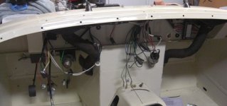
I bought a wiring harness from Austin Healey Spares. My original harness was shot, with frayed wires and most of the cloth covering gone. A number of modifications had been made to the harness also. I tried labeling connections the best I could before I removed the original harness from my car. I thought I could match up harnesses, but I can not tell where most of the wires went at this point on the original harness. I have a wiring diagram from the orgiginal BMC workshop manual, and a diagram from Prospero's garage. I do not find these realy helpful at this point, and I am pretty frustrated. Can anyone help me out? Any help would greatly be appreciated.
Kevin
 

Whitephrog

Luke Skywalker
Country flag
Offline
Kevin

Send me an email address and I'll send you some photos that will help.
 

Brian_James

Jedi Hopeful
Country flag
Offline
I would suggest you ignore the original harness. This can be done, and the best part is that the more connections you make the fewer you have left, the easier it gets to figure out the rest.


I sat down with the new harness and the diagram and started labeling the wires with masking tape. Once you have done that you can lay out the new harness in the car by putting the labeled ends near the corresponding accessories. Start by pulling the branch of the harness for the under hood accessories though the firewall(horn, ignition, generator, voltage regulator and fuse block) ends that plug into the headlights). Position the wires from this branch near their final location (for the horn on the inner right fender and work back towards the firewall-- generator connections near the generator--ignition connections near the distributor...). Once you have that accomplished, I think you will find that you can do the rest. Just work your way towards the rear of the car, laying out the main trunks of the harness and connect the ends one switch / device at a time. It will become obvious, but I would not waste your time looking at old harness.

Brian
 
OP
I

ichthos

Darth Vader
Country flag
Offline
I am kind of doing as you suggest, Brian. I currently have the dash out of the car, so I decided to take advantage of this fact and start there. I layed the wiring harness out to see what wire was close to what. Between the old wiring harness and wiring diagrams, I have about half the wires correctly labled as you suggested. One problem I have is not knowing exactly where each wire goes. For instance, on the panel switch, it shows the two red and white striped wires going to one side and the solid red one going to the other side. The problem I have is that I don't know which wire goes to which side on the switch. Another example is the turn indicator switch. I can identify the 3 wires that go to this switch, but I can not tell which wire goes to which post. Since each of the 3 wires are colored differently, it must make a difference what goes where. Hopefully with help from members on the forum I can get this figured out. I am a whole lot better at looking at pictures than reading a wiring schematic. I will be taking lots of pictures through this process to hopefully help another novice such as myself later. I am very happy with my wiring harness, but I would have glady paid more to have it labeled if this was available.
Kevin
 

Brian_James

Jedi Hopeful
Country flag
Offline
It doesn't matter which side you put you put the red/white vs. red wires on the panel switch. Either side will work. On the turn signal, look at the wire color for the right side front or rear turn signal bulb, and that will tell you where to hook it up on the switch.

The GR (green red) wire runes to the left hand signal lights (#39 and #40 on the diagram) and runs to the switch (#41) the GW (Green with white stripe) runs to the right hand lights, and should be on the right side of the switch. GN (green brown) is the power to the switch, and it should run to the center post. If you have a multimeter just check for continuity between post in all three positions, and that should tell you how it hooks up. I think that once you have made a few of the connections the rest will all fall into place. At least that is how it worked for me.

I used the diagram in the original book.
https://www.gerardsgarage.com/Garage/Tech/WiringDiagrams/wiringdiag.jpg

https://www.gerardsgarage.com/Garage/Tech/WiringDiagrams/wiringkey.jpg

Brian
 
OP
I

ichthos

Darth Vader
Country flag
Offline
Brian, every thing I have done on this car has been a first for me. Almost all of what I have learned is from reading or from members helping me on the forum. When you say right or left, are you talking about me as I am sitting in the car? I do not understand how to use a multimeter to check to see if a wire is hooked up correctly either. If you were explaining how to do this to a 5th grader, using the turn indicator as an example, what instructions would you give them?
Kevin
 
OP
I

ichthos

Darth Vader
Country flag
Offline
I looked on the back of the turn signal indicator switch. On one side there is a tab with the number 2. On the other side are two tabs with the numbers 7 and 8.Do these mean anything?
 

Brian_James

Jedi Hopeful
Country flag
Offline
That's fine. Right hand side sitting in the car, also the passenger side in the U.S.. Get a cheap multimeter from sears, lowes, or even harbor freight. You could also do it with a test light, but a multimeter will be better in the long run. You want to measure resistance (ohms symbol: Ω). Infinite ohms is an open circuit or switch (off) and close to zero ohms is a closed switch. For checking resistance it does not matter which color lead you use from the multimeter (red or black makes no difference). The best way to figure this out is get a multimeter and play with it on the ohms setting (ohms symbol: Ω) by touching the leads together and separating them.

From memory, the turn indicator example would be. With the multimeter set to ohms, if you touch one lead to the center post and the other lead to the post on the right, with the switch in the right position you should get a reading near zero ohms (similar to what you see then you touch the two leads together), with the switch in the middle position or to the left you should get a reading of infinite ohms (the same output you get when the leads are touching nothing).

Hope this helps,
Brian
 

Brian_James

Jedi Hopeful
Country flag
Offline
ichthos said:
I looked on the back of the turn signal indicator switch. On one side there is a tab with the number 2. On the other side are two tabs with the numbers 7 and 8.Do these mean anything?

Yes they do but I can't tell you. One of those posts if for the power to the switch, and the other two are for the right and left side. You can test this with a multimeter. The left and right terminal will never give a reading of zero ohms in any switch position (between the left and right). The common power post (GN wire goes here) will read zero ohms to the left post when the switch is in the left position (GR wire goes to left post), and zero ohms to the right post (GW wire) when the switch is in the right position.

Brian
 

smaceng

Jedi Knight
Country flag
Offline
Another tool which is a little simpler to use is a continuity checker. It usually has a battery and either a light or a buzzer and two test leads. When the leads are connected, the light or buzzer sounds. This allows one to easily check out the path for the electricity through the various components. It will also be a help to check out, sometimes with an extension wire on one of the leads, the opposite end of a dashboard wire in the engine compartment or the rear. Good luck! I recently finished by BE wiring, and found the continuity checker very handy.
Scott in CA
 

Jim_Gruber

Yoda
Country flag
Offline
Can someone post for his benefit the trick about placing a fuse between the harness and the battery so as to keep from burning up the new harness the first time power is applied. I think I know where to place it but can someone who has been down this road before teach him how to not let the smoke out of the wiring harness,

Also Kevin, when using a multimeter don't try to test resistance or continuity if harness is connected to the battery. IF you do so you will smoke the meter. You need to change the indicator / switch on the meter from Rx1, Rx10 Resitance Scale to 25VDC or 25 Volts Direct Current. When using as a volt meter, the Black wire connects to ground(assuming a Negative Ground Here) and the Red Wire touched against the wire should read 12.5 volts.
 
OP
I

ichthos

Darth Vader
Country flag
Offline
I will probably drive you guys crazy with questions, but how do I know if my car was positive or negatively grounded? Just so you know where I am at, my car is basically gutted. I have a new paint job. All I have in is the brake lines and rear end at the moment. I have a few things installed in the engine bay, but that is it. I would like to have it negatively grounded so I can hook up a power source and radio. I do not have a battery at the moment, but burning up my new wiring harness was something I am worried about.
Kevin
 

smaceng

Jedi Knight
Country flag
Offline
A bugeye has a brown wire which is connected to the battery terminal, or maybe to the battery cable at the starter solenoid. this wire supplies goes through the firewall and connects to the wire harness. The harness supplies power to the lighting/key switch and to the voltage regulator. A good idea is to put a fuse into the brown wire where it is connected to the battery. A 5 amp fuse will just about let you run any one single device on the BE, without it blowing. I would use a quick blow fuse rather than a slow acting one.

Being the engineer that I am, I connected a VOM in the series with the brown wire and read the current draw. That way I could connect wires to the harness and such and then just strike the brown wire to the battery. If the current was too high, I could then check it out. In my case, I didn't have any troubles.....SO FAR!
I'm going to try to start it up this weekend!
For a BE, it does not matter if it is positive or negative ground. One can polarize the generator, and be good to go. If you need more help, I would search based on battery, and there have been some good discussions recently along this line. If you still need more help, let us know.
Scott in CA
 

Jim_Gruber

Yoda
Country flag
Offline
A negative ground car has the negative terminal of the battery going to the frame while a positive ground car put the positive terminal to the frame and negative to the wiring harness. There evidently was some rationale for doing this in the past but no clue as to why. Spridgets were positive ground through 67 I believe. Fortunately all of your instruments will work positive or negative ground. Generator can be repolarized, we'll tell you how to do that when you get to that step. And I think you said this is a BE you are working on tach is mechanically driven.
 

tdskip

Yoda
Country flag
Offline
<span style="font-weight: bold">Hang in there</span> - as was said each connection you make starts limiting the number of things to think about. Ask lots of questions and don't assume the current wiring is correct.

I think it's great you are going after this and believe me that you'll be happy you fought though it in the end.
 
OP
I

ichthos

Darth Vader
Country flag
Offline
Thanks for the encouragement. Still many questions.

How do you know if a generator has been polarized or not? My car was in pieces when I bought it, so I am not sure what has been done previously. What would happen if I hooked everything up and the generator was not polarized?

Also, has anyone recently ordered a wiring harness from Austin Healey Spares? I ordered the wiring harness with the cloth covering. I also ordered the dip switch section. I am missing the section that goes through the bonnet, and a short 4 foot section that connects from the main harness, comes out just below the master cylinder, and then heads toward the engine (not sure what it goes to.) Could soomeone tell me what the part numbers are to order these?

Thanks again for all of your help.
Kevin
 

smaceng

Jedi Knight
Country flag
Offline
The BE has 5 sections of harness. Not sure how each vendor pachages it, but here they are.
1. Main harness from dash to the engine
2.Rear harness from the rear of BE to where it connects to the main harness at the outside of the right front firewall
3. Short harness which connects from the dip switch enters the engine area and connects to the right front main harness.
4. Main bonnet harness with connects to the main harness at the right front firewall.
5. Short bonnet harness which connects the right side lights to the left side under the bonnet.

Kevin, sounds like you have the main harness and the dip switch harness and may be missing the bonnet harnesses and maybe the rear harness.
Good luck. I have been told that all of the wiring harnesses for the Sprite are made by one company in the UK.
The picture is from my BE where I have added additional fuses to help save the BE from a horrible death of heat and oxidation.
Scott in CA
 

Attachments

  • 20922.jpg
    20922.jpg
    72.1 KB · Views: 187
OP
I

ichthos

Darth Vader
Country flag
Offline
Ok, I feel like an idiot. I forgot I had removed the bonnet section of the wiring harness and already put it in. I still need to know about the polarization, however.
Kevin
 
Similar threads
Thread starter Title Forum Replies Date
Rut Wanted, Bugeye wiring harness Spridgets 0
Rut Bugeye wiring harness Spridgets 2
D New custom Bugeye wiring harness Spridgets 39
Rut Bugeye wiring harness Spridgets 32
I Bugeye wiring harness pathway help Spridgets 4
I bugeye bonnet wiring harness fasterner help Spridgets 16
tony barnhill Bugeye Wiring Harness Spridgets 0
I New Bugeye wiring harness? Spridgets 17
Ohiobugeye Bugeye Rear Wiring Harness Route???? Spridgets 1
B Bugeye Electrical Wiring Diagram in Logic Format Spridgets 17
B Bugeye Sprite Wiring Diagram Spridgets 4
D Bugeye Wiring Progress. Spridgets 3
D Bugeye Wiring Diagram - First Draft Spridgets 10
AN5Sprite WTB Bugeye/Lucas Wiring Piece Spridgets 1
E Bugeye Wiring - New Fuse Block Spridgets 9
I bugeye wiring help please Spridgets 2
I Bugeye heater wiring help Spridgets 5
I Bugeye headlight wiring help Spridgets 6
I Bugeye wiring help for front turn indicator Spridgets 13
I Bugeye wiring pic needed Spridgets 4
marcm Bugeye Wiring and Brake Line Diagrams Spridgets 0
Bruce_B Wiring up my 58 Bugeye - Questions Spridgets 9
drooartz Bugeye Wiring pictures Spridgets 1
T Bugeye wiring question [last one - really!] Spridgets 10
N Bypassing/Hot wiring a bugeye Spridgets 10
T Bugeye Ignition Wiring Spridgets 10
G Wiring an electric tach in a Bugeye Spridgets 5
R Bugeye ignition switch Spridgets 2
T Music Video with a Bugeye, plus a hill climb video Spridgets 1
D For Sale 1958 Bugeye Sprite Austin Healey Classifieds 3
Todd78d Bugeye carpet Spridgets 7
L For Sale original Bugeye SU H1-1 1/8 Carbs Spridgets Classified 0
Todd78d Bugeye choke linkage Spridgets 5
J Installing Adapter Hubs for Wire Wheels on a Bugeye Austin Healey 5
R Wanted Bugeye ignition switch Spridgets Classified 2
drooartz Replacing Bugeye windshield rubber Spridgets 6
CARSINC 1965 Sprite Bugeye Spridgets 5
drooartz The great Gordon Murray has a Bugeye! Spridgets 0
W Bugeye Tudor Wash Bottle Decal Spridgets 0
R Bugeye drum brakes Spridgets 7
SNClocks Moss Motors 5-speed install in a Bugeye Sprite Spridgets 2
SNClocks Bugeye Alignment Spridgets 4
R Wanted Looking For A Rear Glass For A Bugeye Hardtop Spridgets Classified 0
S For Sale Bugeye wheels, steel with round holes set of 5 available Spridgets Classified 0
D Wanted Bugeye bonnet (hood) fiberglass or steel Austin Healey Classifieds 0
M Wanted Need 59 Bugeye Dashboard. LHD. Spridgets Classified 1
J Finally getting (re) started on the Bugeye Spridgets 27
drooartz Restoring Penny the Bugeye Spridgets 22
drooartz Bugeye jack points to remove rear axle Spridgets 18
B Wanted Bugeye front bonnet fender mirror like this Spridgets Classified 5

Similar threads

Top