 Hey there Guest!
 Hey - did you know if you click on the title of a thread it will take you to the first unread post since you last visited that thread?
 but were afraid to ask:
  STOP!! Never post your email address in open forums. Bots can "harvest" your email! If you must share your email use a Private Message or use the
  smilie in place of the real @
 Pretty Please - add it to our Events forum(s) and add to the calendar! >>

Offline
I received two failed capacitors (I use that term, not the older term "condenser") from Scott Westgate (thanks!) and dug into them today. As a result, I think I know why these things are failing. Anyway, here is the story...
I examined three capacitors, the two failed ones from Scott and a third, unused one of mine, as a control. These are numbered 1 to 3; mine is no. 3 (first picture). Nos. 1 and 2 were distinctly different, apparently from different manufacturers. Mine was marked "Made in England," so it could have been a Lucas unit, but I'm not sure.
Electrical Tests
First, I tested all for open or short circuits. All were OK. Next I checked the capacitance, and all seemed OK this way too, with capacitances between O.20 and 0.22 microfarads (the spec is 0.18 to 0.25). Surprisingly, they seemed to be working. I also checked to see if there was any breakdown. Since the ignition system subjects them to about 250 volts, peak, it seemed possible that the high voltage might have blown a hole in the insulation, and this would not be evident at low-voltage measurement but would allow arcing at high voltages. I don't have a high-voltage power supply to test this, but I did cobble together enough to get 175V. They all held up OK to this level, at least.
Physical Examination
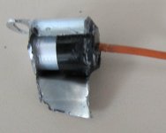
Next I disassembled them. I was looking for a sign of failure, such as arcing across the capacitor or through the dielectric. Here's where things got interesting.
I started with no. 1. I ground off the edge of the case, so it could come apart (second picture). Inside was a capsule (the capacitor itself) and a corrugated nickel-plated contact. The other contact was a brass washer to which the wire was soldered. The capsule, as I'll call it, consists of two layers of foil with a thin mylar layer between the metal layers. It's all rolled up into a cylinder, with one metal layer sticking out one end and the other layer sticking out the other end. Electrical contact is made to the ends, by simply squashing it all together. The capsule is smaller than the can in which it is mounted, so it conceivably could wiggle around a bit in response to shock and vibration. Not good.
The whole thing is a stunningly cheap, unreliable design. There is nothing to keep some force on the capsule contacts; without this, there is no guarantee that the electrical contacts remain good, especially considering the fact that the mylar will expand and contract somewhat with temperature changes. There should some kind of spring, to keep the pressure on the contacts, but there is absolutely nothing, not even anything the least bit springy. The lack of any support for the capsule is also troubling, as it allows it to move around if it comes loose, which will also affect the electrical contacts.
This is all especially important, since the capacitor carries a surprisingly high current. I estimate it at about 2.5 amps, peak. This means that even a small additional resistance is likely to affect the ignition pulse and waveform, with serious affects on the operation of the car.
I started by unwrapping the capsule, so look for signs of insulation breakdown (third picture). There were none. I then took a look into the can and examined the corrugated washer, and saw some clear indications of arcing at the contact points between the washer and the can. This is shown in the fourth picture, although it's hard to see in the photo, especially inside the can. It is quite clear in real life, though.
No. 3, the presumed Lucas cap, was a little better quality, but not much (pictures 5 and 6). There were no marks inside it, which is no surprise, since it was unused. It had no corrugated washer, so the can-end electrical contact was simply to the body of the can, and the other contact was a brass piece that was crimped to the wire instead of being soldered. Again, the whole thing was simply squashed together with no spring of any kind to keep the pressure on the capsule. The capsule was also considerably smaller than the inside of the can.
I finally opened no. 2, and that was quite a surprise. While its design was very similar to 3, it showed clear indications of significant arcing at the can end. Not only were there marks on the can, but there were marks on the capsule as well. It had arced quite a bit (picture 7).
Conclusions
it appears to me that, because of a stunningly boneheaded design, these capacitors are failing because of a poor electrical contact at the can end of the mylar/foil capsule. Since there is nothing to maintain pressure on the capsule, eventually it starts to loosen, because of temperature variations and/or vibration, and the can end begins to arc. This creates additional resistance, and may even cause an intermittent open circuit in the capacitor, which in turn results in bad operation, burned points, and ignition failure. It is also consistent with reports that new capacitors often seem to work well for a period of time, then fail.
What to Do About It?
Frankly, I find the stunningly poor quality of these components more than a little disturbing. I view these capacitors as time bombs in the ignition system. The chance of one failing, sooner or later, is pretty high. Such sloppy manufacturing and design quality really should not be tolerated in cars that have enough potential reliability problems already.
So, what to do? Best bet, in my opinion, is a commercially available capacitor that might be a good substitute. One option that looks good to me is a "snubber" capacitor. These are designed for soaking up large voltage spikes, much like what the capacitor in an ignition system should do. They are not cheap by capacitor standards, a few bucks, but not expensive by automotive standards. I'll look around, and post again when I've found something that looks good. I don't use a conventional ignition system any more, so I'll need volunteers to test whatever I come up with.
I examined three capacitors, the two failed ones from Scott and a third, unused one of mine, as a control. These are numbered 1 to 3; mine is no. 3 (first picture). Nos. 1 and 2 were distinctly different, apparently from different manufacturers. Mine was marked "Made in England," so it could have been a Lucas unit, but I'm not sure.
Electrical Tests
First, I tested all for open or short circuits. All were OK. Next I checked the capacitance, and all seemed OK this way too, with capacitances between O.20 and 0.22 microfarads (the spec is 0.18 to 0.25). Surprisingly, they seemed to be working. I also checked to see if there was any breakdown. Since the ignition system subjects them to about 250 volts, peak, it seemed possible that the high voltage might have blown a hole in the insulation, and this would not be evident at low-voltage measurement but would allow arcing at high voltages. I don't have a high-voltage power supply to test this, but I did cobble together enough to get 175V. They all held up OK to this level, at least.
Physical Examination
Next I disassembled them. I was looking for a sign of failure, such as arcing across the capacitor or through the dielectric. Here's where things got interesting.
I started with no. 1. I ground off the edge of the case, so it could come apart (second picture). Inside was a capsule (the capacitor itself) and a corrugated nickel-plated contact. The other contact was a brass washer to which the wire was soldered. The capsule, as I'll call it, consists of two layers of foil with a thin mylar layer between the metal layers. It's all rolled up into a cylinder, with one metal layer sticking out one end and the other layer sticking out the other end. Electrical contact is made to the ends, by simply squashing it all together. The capsule is smaller than the can in which it is mounted, so it conceivably could wiggle around a bit in response to shock and vibration. Not good.
The whole thing is a stunningly cheap, unreliable design. There is nothing to keep some force on the capsule contacts; without this, there is no guarantee that the electrical contacts remain good, especially considering the fact that the mylar will expand and contract somewhat with temperature changes. There should some kind of spring, to keep the pressure on the contacts, but there is absolutely nothing, not even anything the least bit springy. The lack of any support for the capsule is also troubling, as it allows it to move around if it comes loose, which will also affect the electrical contacts.
This is all especially important, since the capacitor carries a surprisingly high current. I estimate it at about 2.5 amps, peak. This means that even a small additional resistance is likely to affect the ignition pulse and waveform, with serious affects on the operation of the car.
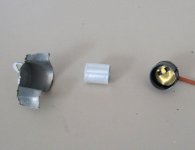
I started by unwrapping the capsule, so look for signs of insulation breakdown (third picture). There were none. I then took a look into the can and examined the corrugated washer, and saw some clear indications of arcing at the contact points between the washer and the can. This is shown in the fourth picture, although it's hard to see in the photo, especially inside the can. It is quite clear in real life, though.
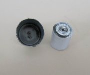
No. 3, the presumed Lucas cap, was a little better quality, but not much (pictures 5 and 6). There were no marks inside it, which is no surprise, since it was unused. It had no corrugated washer, so the can-end electrical contact was simply to the body of the can, and the other contact was a brass piece that was crimped to the wire instead of being soldered. Again, the whole thing was simply squashed together with no spring of any kind to keep the pressure on the capsule. The capsule was also considerably smaller than the inside of the can.
I finally opened no. 2, and that was quite a surprise. While its design was very similar to 3, it showed clear indications of significant arcing at the can end. Not only were there marks on the can, but there were marks on the capsule as well. It had arced quite a bit (picture 7).
Conclusions
it appears to me that, because of a stunningly boneheaded design, these capacitors are failing because of a poor electrical contact at the can end of the mylar/foil capsule. Since there is nothing to maintain pressure on the capsule, eventually it starts to loosen, because of temperature variations and/or vibration, and the can end begins to arc. This creates additional resistance, and may even cause an intermittent open circuit in the capacitor, which in turn results in bad operation, burned points, and ignition failure. It is also consistent with reports that new capacitors often seem to work well for a period of time, then fail.
What to Do About It?
Frankly, I find the stunningly poor quality of these components more than a little disturbing. I view these capacitors as time bombs in the ignition system. The chance of one failing, sooner or later, is pretty high. Such sloppy manufacturing and design quality really should not be tolerated in cars that have enough potential reliability problems already.
So, what to do? Best bet, in my opinion, is a commercially available capacitor that might be a good substitute. One option that looks good to me is a "snubber" capacitor. These are designed for soaking up large voltage spikes, much like what the capacitor in an ignition system should do. They are not cheap by capacitor standards, a few bucks, but not expensive by automotive standards. I'll look around, and post again when I've found something that looks good. I don't use a conventional ignition system any more, so I'll need volunteers to test whatever I come up with.


 A friendly reminder - be careful what links you click on here. If a link is posted by someone you don't know, or the URL looks fishy, DON'T CLICK. Spammers sometimes post links that lead to sites that can infect your computer, so be mindful what you click.