• The Roadster Factory Recovery Fund - Friends, as you may have heard, The Roadster Factory, a respected British Car Parts business in PA, suffered a total loss in a fire on Christmas Day. Read about it, discuss or ask questions >> HERE. The Triumph Register of America is sponsoring a fund raiser to help TRF get back on their feet. If you can help, vist >> their GoFundMe page.
  • Hey there Guest!
    If you enjoy BCF and find our forum a useful resource, if you appreciate not having ads pop up all over the place and you want to ensure we can stay online - Please consider supporting with an "optional" low-cost annual subscription.
    **Upgrade Now**
    (PS: Subscribers don't see this UGLY banner)
Tips
Tips

TR2/3/3A Steering Wheel Restoration

DornTRoriginal

Jedi Hopeful
Gold
Country flag
Offline
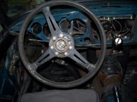
I need Help.jpgI am thinking a head a bit, I was disappointed when my car was at the body shop the steering wheel was left out in the sun and elements and treated with absolutely no respect. I believe the steering wheel is a focal point of the car’s interior and I’d like to think I can bring it back to its original shin and luster. I'd like the wheel and horn button etc. to be sharp! I was looking through the new Eastwood catalog and I saw there is a steering wheel restoration kit boosting to restore cracked steering wheels. My steering wheel is not cracked, a little chipped, discolored and faded. Does anyone have any experience with the Eastwood steering wheel restoration kit?

I did a search of BF and there was a reference to a link on “wiki” for steering wheel restoration advice but the link was not working/available, anyone know where I could find the article?
BTW I got a quote from a "professional" at a car show to do the job, he wanted to a complete rebuild, the cost was just $2K, yikes!:rapture:


Thanks!
 

BillyB62

Jedi Trainee
Country flag
Offline
Just FYI - I bought/replaced my steering wheel from Macy's Garage - https://www.macysgarage.com/myweb6/wood_wheels.htm and couldn't be happier. His neighbor builds them on the original wheel so the control head is stiff fully functional. Not cheap, but it looks beautiful (and way less than $2K). Besides the OD transmission and stainless steel exhaust, this is the only big ticket indulgence I've put into my car.
 

Geo Hahn

Yoda
Country flag
Offline
For a budget resto of the steering wheel (which can yield good results) any cracks or chips can be filled with JBWeld and sanded to the correct contour. Color restoration can then be done with spray 'paint'. Paint in quotes because I used an SEM product but now there are other choices for effectively painting plastic.

If mainly faded from sunlight - you might try a light wipe of linseed oil to see if that revives it to your liking.
 

TR3driver

Great Pumpkin - R.I.P
Offline

Kleykamp

Jedi Trainee
Offline
Also did the JBWeld on cracks and sanded and painted the wheel with plain enamel from the auto parts store. That was four years ago and it still looks good. It could have looked even better if I had taken more time sanding. I also used JB on the control head where a piece was broken out and painted it. Required a little more effort to get the "beveled" edge right. No way does it take $2K to get one looking good or even perfect. I've seen someplace where a woodworker is restoring them into wood wheels and the ones I've seen are nice. Sometimes a heat gun will restore the gloss to plastic, but have not tried that on older types of plastic. The real problem I had was getting the grub screws out to remove the control head from the wheel. I had to drill and retap those which is a little problematic for the ill equipped.
 

charleyf

Luke Skywalker
Country flag
Offline
For a budget resto of the steering wheel (which can yield good results) any cracks or chips can be filled with JBWeld and sanded to the correct contour. Color restoration can then be done with spray 'paint'. Paint in quotes because I used an SEM product but now there are other choices for effectively painting plastic.

If mainly faded from sunlight - you might try a light wipe of linseed oil to see if that revives it to your liking.

i as well used JB Weld to restore the wheel and then used quality spray paint over that. I would put my wheel up for inspection against any $2k restoration. Not bragging here, just saying that it is not that hard to do if you take your time and try to do a very good job.

Charley
 

6TTR3A

Jedi Warrior
Country flag
Offline
Basically the same story for my wheel. I used laminating resin instead of JB Weld. Mine had some GIANT pieces missing. Finished it off with 25 coats of gloss black lacquer. That was in 1989. Still looks factory fresh!
Frank
 

TRMark

Jedi Knight
Bronze
Country flag
Offline
On my TR4 steering wheel the weld broke fastening the spokes to the steel hoop. I cut away the plastic and welded it. I replace the cut and melted plastic using POR15 epoxy putty. Very easy to work with then primed and painted. I had some bad cracks on a my John Deere 41B filled them with the epoxy putty.
 

sp53

Yoda
Country flag
Offline
Glad to see this post because I am waiting for the weather to dry out and warm up, oooOH Seattle. Anyways mine seems to pealing apart in layers and I figured it was toast, but you guys gave me hope. It looks like the first layer only maybe the second, so I will follow along and do some sanding and filling and painting. Were the original wheels a high gloss or semi-gloss? I like the looks of the wheel and I too believe the stock look of that big wheel is important for the classic look.
 

sp53

Yoda
Country flag
Offline
I have 2 wheels I am doing and the one which is ugly I filled the cracks with JB and waiting on that to cure before painting. The other which is in better shape I sanded the flacking and pealing then cleaned it with SOS and I might just leave it that way. It is a little faded and still needs more sanding, but I like natural and patina look. Someone said to try linseed oil, and I was think about 400 paper and some buffing. Anyone have suggestion on how to buff plastic?
 

John_Progess

Jedi Warrior
Country flag
Offline
I always buff all the plastic, fuse block, voltage regulator, switch knobs, gear shift knob etc. with a buffing wheel and compound made for plastics. Everything comes out shinny as new. I have not buffed a steering wheel as I always cover them with leather Wheel Skins. Have a good day!

John
 

charleyf

Luke Skywalker
Country flag
Offline
The one thing NOT to do is use any high speed tool. For me even the softest wheel melted the plastic. So I would say by hand, keep going for finer sandpaper like 1200 or so. I am guessing that there are some compounds available to help as well.
Charley
 

AHS

Senior Member
Country flag
Offline
My TR3 wheel originally looked bad, with a rough brownish surface, and only one crack. It sounds like yours is similar. The process was:
-Blast the hub clean with walnut shells
-Epoxy the crack with black epoxy (JB weld is gray, look for black)
-Sand by hand with 1000 & 2000 grit exactly as I did on the body clearcoat
-Use the same polishing compounds as on the body clearcoat, except I applied them by hand with a paper towel until it was high gloss
-Polish the spokes with chrome polish by hand
-Paint the hub with rustoleum gloss black
When the man from whom I bought the car saw it, he asked where I had obtained that nice steering wheel. He was surprised it was the same wheel.
Andy
 

Born_Loser

Member
Offline
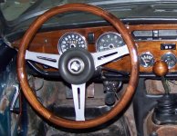
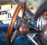
If anyone feels like making a wooden wheel out of the original, I did one for the Spit. Came out very well, was easy to do, and the thickness can be adjusted to your preference. Simple tools, and simple woodworking skills. Let me know if anyone is interested in the "how to".

100_2815.jpgWheel after.jpgWheel back.jpg
 

Born_Loser

Member
Offline
Sure thing. I actually used a DIY Tut from a guy that did this for an MGB. Guys name is Mitch, and you can probably find it via Google if you wanted. I modified it a good bit, and gave detail on the sigtht Mitch's is posted on. I will copy that over, and answer any questions you might have.

Why did I do it? The dash and steering wheel were shot on our father-son build. My son wanted a dark dash. and after reading Mitch's tut, I figured a matching wood wheel would look much better than a leather wrap (the alternative).

What tools did I use: I have a fairly good selection of wood working tools, but, for this project, there really is only 1 tool you MUST have - a router. I can see lots of ways to get each step done, but without a router, you just can't cut the groove for the steel rim. A bench, or table, for the router, makes the round overs easy, but, even that is not required if you are going for a more squared, Classic Moto-Lita style rim. I use a router that can be mounted on the bench, but also has a "plunge" base - this is not required, but makes the circle cuts very easy. I also used a chop saw/electric miter saw. Mine is a very inexpensive one, but I did put a thick blade on it- to prevent any bending or movement during the cut. These cuts could be made with a miter box and a hand saw in a pinch, but they are important - accuracy to hit 30° is required. A table saw could also make these cuts, but, then each piece being exactly the same length gets a bit tricky. Not 100% required, but I also used a band clamp, as well as 6 small clamps. In addition, I made a few tools. 1) An angle/length stop on the miter saw. Made out of scrap 2) A drum sander out of a hole saw. a strip of sandpaper, and some tape. 3) A wheel clamp, out of the left over routing scraps.

Choosing the wood:I mixed up some stains, and tried them on different woods, and my son settled on Walnut, with a 50/50 mix of American Walnut/Gun stock for the finish. I needed enough wood for the dash, the steering wheel, and a shift knob. I looked around locally, and folks were very proud of their wood selections. I looked on Ebay, and found allot of Walnut very inexpensive. I found a lot that had 3 boards, and one was big enough to make the entire dash out of - so the grain would line up. The other 2 pieces had enough wood for the wheel and the knob. Only down side, it was thick. 1 inch thick. But, it was $14, and I had it in hand in a week.

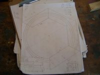
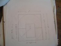
Making a plan: I relied heavily on Mitch's tut on the size of everything, and how the steel would mount. After giving it thought, I also agreed a hexagon, 6 equal sides, was the way to go. I had wide enough wood, I could have just put 2 pieces together, and there would only be 2 seems in the whole thing. But then, they grain would not be going in the right direction very often, and I liked the look of the segments as well. So, maybe 8? Too many seams, it was too busy, and segments looked chopped up. 6 was just right. I also agreed with the 1 inch wide by 1" 1/8 deep wheel itself. You will see, you can make things as wide as you like very easily. The depth will be determined by how thick your 2 or 3 pieces of wood are. Next up was the diameter. I cut a little bit of the old grip away. 2 spots, 180° apart. Then I measured from center to center of the steel rim. This would be the center of the groove in the wood rim. For my '70 Spit wheel, that was 14 1/4". I had made a drawing based on Mitch's dimensions, and I updated it for the Spit. There would be 2 hexagons - the top, and bottom - so, I would need to cut 12 trapezoids 9 5/8" X 5 3/4", 3" wide, with opposite 30° angles. I did not want an accent piece, so one would be 5/8", and one would be 1/2" (1 1/8" total thickness).

Trimming the stock Thickness is a preference, and can be achieved several ways. This project could easily be made to 1", if all you have access to is 1/2" thick wood. Or, as Mitch did, add a 1/8 layer. Or as I did, make 2 different thicknesses out of 1" lumber. The easy way to make a 1" board 1/2" is to run it through a planner. "My" planner is actually still my dads planner, with my name on it in his Will. And he lives about 1500 miles away. So, I had to come up with another plan. Knowing I would be cutting off the corners of my 7 1/8" X 51" boards helped. Also knowing I would be using very little of the face meant it did not have to be perfectly smooth - another +. So I chucked a straight cut bit (plunging) into the router, and mounted it on the bench. I took off about 3/8 at a time, and left "feet" for the board to be supported on across the bench. When the board was the proper thickness, I slowly "plunged the router on the "feet" I had left, until they were level with the rest of the board. Kinda crude, I wouldn't want my formal dinning table made that way, but worked just fine for this. Next was the width. My mock up drawing called for 3" boards. 3 1/2 is normal for purchasing, so if that is what you have, it will work fine. I ran mine through the table saw, to get a clean edge, and that left it 3".

100_2883.jpg100_2884.jpg
 

Born_Loser

Member
Offline
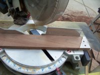
Cutting the trapezoids: In the bottom left of my drawing, you see the dimensions of the trapezoid. The lengths are not that critical, they determine the diameter. The important part of the length, they need to all be the same. One of the most critical cuts of the project is getting this angle correct. It should be 30° exactly. You will be putting this angle together 12 times. If its 29°, you will only have 348° of your required 360°. 29.5° is still 6° short, the last piece simply will not touch the first piece on assembly. A couple things to help with this. 1) Like Mitch, I used a 30/60/90 from my drafting set to set the blade, and check the cuts. My saw was off just a smidge (smidge x 12 = 2°). While cutting, I saw my blade "wonder" just a bit after it started cutting. I swapped the very light and thin blade (and probably a bit too dull) with the old planner blade my dad gave me (a bit early - he is still alive and healthy). That sucker is thick, and did not deflect at all - yielding a very straight cut. Next I cut 6 pieces the same length (very short, just checking the angle, not the size) of scrap, and found the angle was just a bit too steep. I made the smallest of adjustments, and did it again. Close enough a tiny bit of sanding on the first piece and last piece brought them together. Next up, I screwed a piece of wood to the end of the miter saw, then set the length with a piece of the last "test" with the correct angle. Now, as long as i pushed my stock against the fence, and the piece I just attached, all the cuts will be the same length. Just needed to flip the stock after each cut.

Strength: There will be very little wood glued to wood at each of the joints, so the strength of each segments joint will be very weak. To address this, Mitch uses slots and splines to beef up the joints. I had a different take. I decided to skip that, I just don't care for the look. My plan was to simply off-set the top and bottom, so the segment joints fall in the middle of the opposite sides segments. That, and glue both top and bottom firmly to the steel rim. The steel will take the load, not the segment joints. This approach means you do have to use care while handling the none-assembled 1/2's.

Making the Hexagons: I simply laid out the pieces, like Mitch, on waxpaper. Added glue to one side, and worked my way around. I used Tightbond III. No particular reason, its just what I have, and has always done a fine job. Use whatever you use. I also used a simple strap clamp. If you don't have one, there are all sorts of ways to clamp it all together. I would probably just use a small ratchet strap - they are about the same thing.

Cutting out the circles - the Circle Jig: I have an incredible router table. Its a cast iron leaf, that is attached to my cast iron table saw. Unlike Mitch, I think cutting circles is best done with a circle jig, so I didn't use either one. My "circle jig" is just a piece of plywood that I drilled mounting screws into for my router. It will work just like Mitch's compass, but instead of drawing a line, it will cut wood. To get the opening for the blade, I just plunged the 3/8 strait bit through the ply wood. It has made allot of circles in its day. for the pivot point, I use a finishing nail. 2 actually. I cut the head off of one, and chuck it in my drill as a drill bit. With the router mounted on the jig, I just measure from the bit edge to my radius, then "drill" a hole in the jig. This is where the finish nail will pin the jig to the center of the circle I am about to cut.

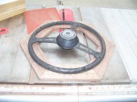
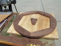
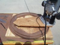
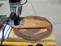
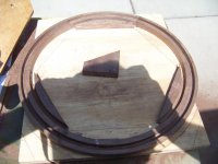
Cutting out the circles - mounting the wheel: The second part is the stock has to be firmly held, and the center (for the finish nail in the jig) needs to be solid. I differed from Mitch on how to do this as well. My idea was to screw the hexagon to a piece of plywood. Then take a piece of scrap (1/2 or 5/8, depending on how thick the hexagon was) and screw it to the center. The screw points would be on the inside middle of the segments, that's the one place the wheel will not go. I found the center by laying a straight edge across the joints, and drawing a line. Where all 3 lines touched is the center. I used my finish nail drill bit, and made it permanent.

Cutting out the circles - the 3 cuts: I drew up a cross section of what I wanted the wheel to actually be when it was done. I wanted to make sure the grove would fit inside the wood. I measured several wheels around, and found that most were not round. They were offset, 3/8 curve on the outside, 1/2 curve on the inside. I kinda liked the idea, so I offset the steel rim grove, to allow for the extra curve. Later, my son, wife, and a few people I don't even really know would tell me that was a bad idea. So I didn't round it off that way, but I did make it that way. You should probably just center your 3/8" grove inside-to-outside that is. The depth I have exactly right on this drawing. 3/16" deep on the bottom piece (the 1/2" piece), and 7/16 for the top (the 5/8" piece). The other tricky part about the 3 cuts, is getting the pin in the correct spot - not just measuring correctly, but knowing WHAT to measure really. It can get confusing. Take your time and triple check before you turn your hexagons into scrap. The thing to remember is you are measuring the radius of your cut, from the INSIDE of the bit. You should be using a 3/8 bit (because the steel rim needs a 3/8 slot). So you have to add or subtract to get the measurement from the bit to the center hole you are about to make with the finishing nail. In this case (assuming the grove is centered outside to inside), the 3 cuts are:
1) Outside diameter: 15 1/4". The radius is 7 5/8". So you measure from the INSIDE of the bit, 7 5/8", and drill your hole. That cut will give you an outside circle of 15 1/4". This is the first cut you make. Start by taking about 3/16" depth, and increase each pass about the same. I use a plunge router for this, it makes the starts much easier.
2) The groove for the steel rim: 14 1/4 centered. Radius is 7 1/8". But that's to the center of your bit - very hard to measure. the RADIUS of your bit is 3/16". So, measure 6 15/16" from the inside of your bit, and make your hole. The depth of this cut is 3/16" for the bottom (1/2" board), and 7/16" for the top (5/8" board).
3) The inside diameter: 13 1/4". The radius is 6 5/8". This cut will be from the OUTSIDE of the bit, so subtract the bit, 3/8" to measure from the inside. That's 6 1/4. Cut your depth as the first one, the Outside diameter, but leave just a tinny bit for the last pass. Then lower the bit just a little, and go around as smoothly as possible, completing the cut.

100_2885.jpg100_2886.jpg100_2895.jpg
 

Born_Loser

Member
Offline
Pic 1, the mount.
Pic 2 The groove cut
Pic 3 The inside cut
Pic 4 Just a bit left of the last cut

Screws with circles around them.jpg100_2897.jpg100_2898.jpg100_2899.jpg
 

Born_Loser

Member
Offline
Shaping the halves: Once both halves are cut out, the should stack nicely. This is a good time to run some 120 grit sand paper around the outside and inside, to get that perfect alignment. I copied Mitch's idea about the pins. I just cut off the heads of 3 finish nails (made them very short, and used a 4th nail as a drill bit. I made a small hole, and pressed the nails in, pointy side up, about 120° apart. No glue, the friction was a tight fit. Next I aligned the top as carefully as I could, off-setting the joints on the top, to the middle of the segments on the bottom, and pressed down. Now the 2 half's had alignment pins, and they would go together the same way from here on out. I made a "drum sander" by taping some 120 sand paper to a 1"1/4 hole saw. Chucked into a drill, and ran around the inside that way.

Preparing the rim: To get the old rim ready, I needed to cut the old padding off of the steel rim. My son came home just in time to get handed a utility knife and a stool. It took a bit, but he got it down to just metal.

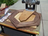
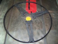
The reliefs: The rim fit perfectly into the groove, and it was reasonably round. The next part was to cut reliefs for the spokes. I decided during planning that this would be done on the bottom piece, and that's why its groove is 3/16" deep - that's the thickness of the spoke. I marked the opening, and took a chisel the first one. It took some doing, to get it perfectly flat. So, I put the router back in the table mount, set the height at 3/16" and made the other 2 cuts perfectly in about a minute. The top was not so easy. Where the spokes joined the rim, there was a substantial weld. I relief would have to be cut out, near the groove, to allow for it. It would not show when assembled. A chisel would have worked here as well, but, I made a blind route on the table, since it was already set up.

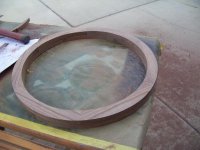
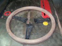
Pic 1 - The finished circles.

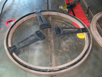
Pic 2 - Marking the reliefs

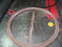
Pic 3 - The reliefs done

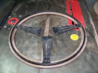
Pic 4 - The reliefs done, rim in place

100_2901.jpg100_2904.jpg100_2905 (2).jpg100_2906 (2).jpg
 

Born_Loser

Member
Offline
Making the "square wheel" round: Mitch opted for a very round wheel. I had decided that I didn't want it that round, so I used a 3/8 round over bit in the router, instead of a 1/2. I would later decide that was "too square", and hand sand it more. This part is personal preference, and I spent allot of time getting it "just right" - for me anyway. The operation was basically exactly like Mitch did it. If you don't have a table, you can sand it by hand, or have a helper hold it, and move with you as you route it from the top.

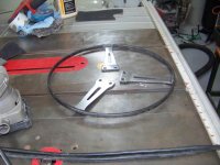
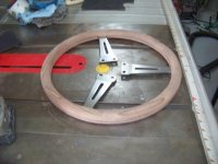
Spokes: The folks at Triumph have had some real great ideas over the years. The "black out package" on the '70 Spit was not one of them. Sorry purist, I have already removed every trace of the black out, except the steering wheel. I am sure in this first photo, your first thought was not "that wood working looks great". It was probably "the black does not work!". I set out to do something about it. The paint was on there really well, so I used a bit of the Spra stripper I had left from the paint job. Next I cleaned it up with 220 in my finish sander. Then 400, 600, 1000, 1500, and then 2000. Hmmm, brushed steel! That look works! When I got the spokes done (the inside of the cuts got a very small drill bit, with the proper grade paper taped to it), i clear coated them.


Pic 1 - Rounded corners
Pic 2 - 1st spoke brushed
Pic 3 - All spokes brushed
Pic 4 - Brushed spokes fitted to the wheel

100_2907 (2).jpg100_2918.jpg100_2925.jpg100_2926.jpg
 
Similar threads
Thread starter Title Forum Replies Date
S 3000 BT7 Steering Wheel Restoration help needed Austin Healey 3
hutten Wood steering wheel restoration vendors? Triumph 2
B TR2/3/3A TR3 Steering wheel restoration Triumph 4
M steering wheel restoration-from the beginning Triumph 17
M steering wheel restoration Triumph 4
Rut steering wheel restoration Restoration & Tools 16
Jim_Stevens Steering Wheel Restoration Triumph 7
PAUL161 T-Series TF Steering Wheel Restoration MG 7
PAUL161 Steering Wheel Restoration. MG 6
PAUL161 Steering Wheel Restoration MG 8
angelfj1 Steering Wheel Restoration - WIKI Restoration & Tools 3
W Momo Steering Wheel Restoration MG 2
healeynut Steering Wheel restoration - advice needed Other British Cars 0
HealeyPilot Steering wheel restoration Austin Healey 4
healeynut Steering Wheel restoration - advice needed Restoration & Tools 7
R Steering Wheel Restoration Kit Austin Healey 5
Tinkerman Steering Wheel Restoration Triumph 3
1965_MGB Steering Wheel Restoration Restoration & Tools 13
Basil Steering Wheel restoration - recommendations? Restoration & Tools 15
T TR6 Steering Wheel Lock Triumph 2
D Removing the steering wheel hub Spridgets 12
K 1968 Midget Steering wheel Spridgets 1
Editor_Reid Wrapped Steering Wheel Austin Healey 9
B TR4/4A Steering Wheel Hub Issues Triumph 0
K TR2/3/3A Who sells steering wheel control head "Allen head'' grub screws? Triumph 5
EWD For Sale ‘74 TR6 original steering wheel Triumph Classifieds 0
S SOLD!! Mike Lempert 15" slotted Derrington Steering Wheel Austin Healey Classifieds 1
kodpkd Leather Steering Wheel Cover Austin Healey 3
S Steering Wheel Brand Austin Healey 5
B TR4/4A What is this Steering Wheel Center? Triumph 6
Martinld123 Steering Wheel Alignment [Lost centering on steering box 1956 Austin Healey, BN2] Austin Healey 14
Celtic 77 MGB Steering wheel fitment MG 11
S TR2/3/3A Steering wheel removal. Triumph 4
LAW75 Derrington Steering Wheel Austin Healey 19
waltesefalcon New steering wheel Other Cars 2
R TR2/3/3A Steering Wheel hitting my belly Triumph 22
bighealeysource T-Series My older Brooklands steering wheel is leaking ! MG 4
A Austin A40 trafficator steering wheel Other British Cars 5
T Steering Wheel Adjustment Range Austin Healey 0
R TR2/3/3A Steering wheel hub removal Triumph 11
K TR2/3/3A Question about installing the steering wheel control head? Triumph 1
J Wanted Adjustable steering wheel circlip Triumph Classifieds 4
E Wanted wanted Austin healey 3000 adjustable steering wheel & dash pad Austin Healey Classifieds 2
Cappy Moto-Lita Steering Wheel Installation Austin Healey 3
K TR2/3/3A Steering Wheel hold down Nut Triumph 6
J Steering Wheel Repair Austin Healey 32
Walter74 Adjustable steering wheel removal Austin Healey 4
D TR2/3/3A Shaking in steering wheel above 50 mph. Triumph 19
G Steering wheel offset Austin Healey 10
D Steering Wheel Repair Austin Healey 2

Similar threads

Top