• The Roadster Factory Recovery Fund - Friends, as you may have heard, The Roadster Factory, a respected British Car Parts business in PA, suffered a total loss in a fire on Christmas Day. Read about it, discuss or ask questions >> HERE. The Triumph Register of America is sponsoring a fund raiser to help TRF get back on their feet. If you can help, vist >> their GoFundMe page.
  • Hey there Guest!
    If you enjoy BCF and find our forum a useful resource, if you appreciate not having ads pop up all over the place and you want to ensure we can stay online - Please consider supporting with an "optional" low-cost annual subscription.
    **Upgrade Now**
    (PS: Subscribers don't see this UGLY banner)
Tips
Tips

TR2/3/3A Accererator Assembly Continuing

DornTRoriginal

Jedi Hopeful
Gold
Country flag
Offline
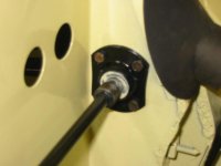
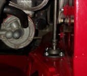
Accelerator Assembly Installed Lft Side (small).jpg
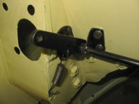
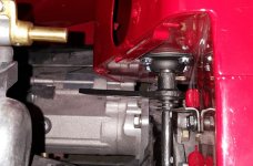
Accelerator Assembly Installed Rt Side (small).jpg~

I have had too much fun getting the accelerator assembly installed, I never been closer to getting it completed. I put everything back in and I want to be sure I have it correct before I finalize the installation, thank you in advance I know I have asked a lot of questions on this particular topic. I ordered new tapered pins due to shipping minimums I have a few extras so if anyone needs some I can mail them to you, I have 1/8 inch x 1/2 inch (long) and 1/8 inch x 3/4 in (long) they were $.33 ea. but the shipping was the killer at $12.00. They are small enough to fit in an envelope so I'll mail them to you if you want a couple. PM me if you’re interested.

First picture is the driver's side (lft), there's a slight gap between the bushing on the rod and the bushing inside the bracket. The second photo is on the passenger side (rt) and shows the position of the lever.

Here's my latest questions and hopefully last ones on this particular subject:

I used cotter pins to put the assembly in the car while waiting for my tapered pins to arrive and just to be sure I am doing the assembly correctly.

  1. The bushing on the driver’s side is about 1/4 of an inch from sitting snug in the bracket holding the nylon bushing. The assembly seems to operate fine my question is if it is better to move the bushing over, drill a new hole to insert the tapered pin in the rod so everything fits tighter and the bushing will fit deeper into the nylon bushing.
  2. I am not exactly certain how the lever arm attaches to the carburetor assembly and throttle, do I have the accelerator arm installed correctly? The way I have it installed when the gas pedal is pushed the lever goes downward and there is a good bit of travel, is the position and angle correct? I am having a hard time visualizing how everything goes back together and I have not found any good diagrams. Does anyone have a good picture of how this all gets assembled?

Thank You! :cool:
 

trglory

Jedi Trainee
Country flag
Offline
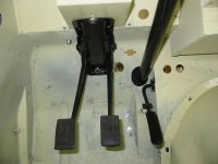
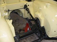
Not quite sure how you have the linkage rigged....when you press the petal, the lever arm goes up and pulls agains the return spring below. See attached pictures.

IMG_0866m.jpgIMG_0865m.jpgIMG_0864m.jpgIMG_0860m.jpg
 
OP
DornTRoriginal

DornTRoriginal

Jedi Hopeful
Gold
Country flag
Offline
You are right, the pedal goes down the lever goes up.....
 

TR3driver

Great Pumpkin - R.I.P
Offline
The lever actually makes more of a fore/aft motion than up/down. That pulls on the bellcrank under the front carb, which in turn pulls the short front rod down and opens the throttle.

The adjustments I look for are in order:
1) The lever on the front carb should angle up at about a 45 degree angle with the throttle closed.
2) The front arm on the bellcrank should be at about the same angle.
3) The pedal should just hit the stop when the throttle is wide open.

I checked the old shaft from my (now wrecked) early TR3A, and it shows about the same amount of exposed metal outside the bushings. Since it held up just fine for maybe 300,000 miles (bushings still original AFAIK), I think that's probably OK :smile:
 
OP
DornTRoriginal

DornTRoriginal

Jedi Hopeful
Gold
Country flag
Offline
Thanks, I am feeling like I got the accelerator assembly installed correctly and I will seal the deal when the tapered pins arrive. I am going to work on getting the petal assembly installed next. Randal I am sorry to hear about your TR3A being wrecked, tragic. :sorrow::sour:
 

TR3driver

Great Pumpkin - R.I.P
Offline
Randal I am sorry to hear about your TR3A being wrecked, tragic. :sorrow::sour:
Not to worry, that was a long time ago. Bound to happen eventually, driving every day on LA-area freeways. Typical off rush hour traffic jam; we'd all been rolling along at 70+ mph then had to come to a stop. The guy behind me was a long way back, so I assumed he'd have no problem getting stopped; but it turned out he was distracted (I overheard him tell the CHP that he was getting a Coke) and didn't stop. I tried to get out of his way, but was too slow. 4 car chain collision, but I was the only one with serious damage.
Crushed the trunk, bent the apron in until it touched a front tire, and shortened the body a few inches at the A & B-posts. The doors still worked sorta, though, I guess they're stronger than they look. I discovered later that one of the front suspension mounts tore away from the frame as well. But I was fine, didn't get so much as a sore neck out of that one.
 

NutmegCT

Great Pumpkin
Gold
Offline
<snip>
Crushed the trunk, bent the apron in until it touched a front tire, and shortened the body a few inches at the A & B-posts. The doors still worked sorta, though, I guess they're stronger than they look. I discovered later that one of the front suspension mounts tore away from the frame as well. But I was fine, didn't get so much as a sore neck out of that one.

Wow - sure glad you survived. In a way, sounds like your TR was a "bumper to bumper" crumple zone - and a very effective one at that.
 

tedwone

Senior Member
Country flag
Offline
OUCH! Do you plan to part the car out? I am in need of a very small piece of sheet metal, low and in front of the left rear wheel well.

Ted
56 TR3
59 TR3A (2)
60 TR3A
33 Standard
62 Jaguar MK2
 

TR3driver

Great Pumpkin - R.I.P
Offline
Sorry, it's already gone. I tried to give the body & frame away after stripping it, but they eventually went to the crusher.
 
OP
DornTRoriginal

DornTRoriginal

Jedi Hopeful
Gold
Country flag
Offline
I am stuck and frustrated…
I put everything together but when I try to install the spring return it's just not right. The first picture is the lever and the gas petal is in the idle position the second two pictures the gas petal is pushed to the floor or in a full throttle position.

When the pedal is pushed all the way to the floor, BTW the bolt/pedal stop on the floor is not installed, the lever arm is not raised enough to engage the spring at all. When the pedal is at rest or in what I would think is the idle position, the arm is just about parallel with the slope/contour of the fire wall and the spring is not at all in a position to be useful. (I checked and it's the correct spring) In looking at the pictures TRglory posted the arm looks like it is in an idle position, the spring is not stretching and it is a good fit sitting at a 90 degree angle to the firewall, I assume when the pedal is pushed the spring is engaged as the arm lifts. Not so in my case. What am I missing here? There are only two ways I figure to install the arm on the shaft, the pedal and shaft can only go in one way through the drivers side of the floor/firewall, if I install the arm 180 degrees from where it sits now the arm would hit the fire wall when the pedal is pushed to the floor and the spring would be too short. Are the holes in the shaft incorrect? When the body shop bent the shaft and attempted to fix it did the whole assembly get ruined? I am also going to see if I can find a replacement I just can't figure this out Arrrrrhhh!
This is really crazy! Thank you for your assistance. I am in an argument with myself over this... :argue: what the heck is wrong?


Accelerator Assembly Lever arm idle position (1).jpg
Accelerator Assembly Lever arm Pedal full open (2).jpg
Accelerator Assembly Lever arm Pedal full open.jpg
 

TR3driver

Great Pumpkin - R.I.P
Offline
Definitely way off, but looks more like 90 degrees to me. Could one of the pins be sheared? Or maybe someone drilled an extra hole in a shaft? There were (at least) two different setups used, could you have a mixture of parts?

The arm does stand nearly straight up, and as I recall will hit the firewall if the pedal stop is removed. The return spring gets stretched a long way even when the pedal is all the way up.
 

charles brooks

Freshman Member
Offline
I'm putting my assembly back in this weekend and would love to have a pin for the passenger side if still available. Thanks much.
Charles
 

sp53

Yoda
Country flag
Offline
TRglory’s picture that he posted here on this question is spot on. Somehow yours is assembled incorrect; perhaps both pins are installed 180 out.
 
OP
DornTRoriginal

DornTRoriginal

Jedi Hopeful
Gold
Country flag
Offline
Thanks everyone, I'm on track now that I found out that the shaft can be twisted... I was able to put the assembly in a vise, as suggested by Marv and eluded by others, and twist it into the correct position. I would never have thought that was possible! Now I just need to get it back into the car. I am sending Charles some pins, I hope he has better luck than I have had with them, my guess is the hole needs to be tapered to fit the pin correctly, which I was not able to do. The tapered pins and the over sized pin did not fit they were either too large and would not seat or too small and fell right out, so I scraped that idea. I decided to thread the holes in the shaft with a 8-32 tapered tap and inserted a socket head cap screw with a lock nut. It seems to be a secure fit and I was able to remove everything while I struggled with the poor alignment issues.

Wow this exercise has cost me a lot of time on ward! Thanks again for all the help I'd still be fussing over stuff with out the assistance!!
 

trglory

Jedi Trainee
Country flag
Offline
When you get it all back in the car and hooked up, post some pictures and let us know if the range of motion in the assembly feels right to you. Install the limiter bolt under the pedal so you can see how far the crank rod pulls the return spring.

Many of us on this forum have already done one or more full restorations. We know what looks wrong because we made plenty of mistakes during the process .... that's how you learn. You read the ROM, look at pictures and keep redoing it until you get it right. And when you run out of ideas, you ask the group. Between all of us, we probably know at least 10,000 things not to do, so keep asking questions and we'll do our best to help you get where you want to be.
 

blhazzard

Member
Offline
For TR4A

Sorry ... late to this thread but I removed the pedal rod assembly to replace the nylon bearings and noticed the support bracket had cut a groove into the shaft due to the nylon bearings being worn so much.
Also the shaft was bent and corroded so much bushing would not come off ...
I am afraid this shaft is going to fail at some point.

I was considering replacing these parts with new (or newish) parts however no one seems to have bushings and shaft assemblies. Moss and VictoriaBritish do not show the parts as available...

Does anyone have the following parts in new or newish shape.
As long as the parts are restorable and not bent I am willing to pay as I plan to clean and chrome them.

1) Accelerator pedal shaft assembly
2) BUSH on pedal shaft
3) BUSH on pedal shaft with throttle arm
4) Support Bracket, Pedal shaft assembly
5) Mounting plate for accelerator rod bearing (four required)

Also I was considering modifying the support bracket to accept a bushing to prevent this grooving again.
Found a bronze 3/8:1/2 (id:eek:d) bushing to insert into the bracket...
Any comments ?
 
Similar threads
Thread starter Title Forum Replies Date
M TR6 Filter housing assembly? Triumph 7
B For Sale GT6/Spitfire License Plate Light Assembly Triumph Classifieds 0
N TR5/TR250 Starter Box Assembly Leak Triumph 14
D TR2/3/3A Windshield assembly question Triumph 6
K TR2/3/3A The horn and turn signal assembly. Triumph 3
G Installing New Rocker Shaft Assembly Austin Healey 3
D TR6 Rocker arm assembly , pushrod clearance Triumph 8
tr6nitjulius For Sale "PRICE REDUCED" 4Sale: TR6 (L/R) taillight assembly Triumph Classifieds 0
Rob Glasgow Check Strap Assembly Austin Healey 5
bighealeysource Drum Brakes Assembly Austin Healey 6
D BT7 Choke Assembly Austin Healey 18
B TR4/4A Ammeter Assembly Triumph 2
Popeye TR4/4A TR4A Assembly by a rookie (me!) Triumph 149
S For Sale TR-3 Tie Rod Assembly for Sale Triumph Classifieds 0
S For Sale Oil Pump Rotor Assembly for Sale Triumph Classifieds 0
M Need help removing the pinion assembly from a late 1275 steering rack Spridgets 7
SherpaPilot TR6 Choke Assembly Triumph 0
Csarneson BN4 Interior Assembly - Unidentified Holes Purpose Austin Healey 2
Kolecki TR2/3/3A engine assembly cam timing issue Triumph 8
F TR2/3/3A TR3A tub assembly Triumph 44
S TR2/3/3A tappet assembly Triumph 10
J RIB CASE MAIN SHAFT ASSEMBLY Spridgets 2
Popeye General TR FS2758 alternate - Door Pull Assembly Triumph 2
Csarneson Body panel assembly order? Austin Healey 6
T Articles by Hap Waldrop reg engine disassembly and assembly Spridgets 1
Michael Oritt SU H6 carb for Le Mans--order of assembly of fuel bowl lid Austin Healey 2
R TR2/3/3A Transmission Lever Assembly Triumph 9
Got_All_4 TR6 drill and tap for a grease fitting tr6 rear hub assembly Triumph 4
steveg Points assembly order of washers Austin Healey 13
Lin Healey assembly line - engine installation Austin Healey 19
K For Sale TR3 Gas Cap Assembly Triumph Classifieds 0
S Wanted Austin Healey heater assembly Austin Healey Classifieds 1
Lin Bonnet Striker Pin Assembly Austin Healey 5
S TR2/3/3A Slight clunk in the rear assembly somewhere. Triumph 3
P TR2/3/3A Rear axle hub dis-assembly Triumph 1
F Which Original Oil filter assembly for BN7 Austin Healey 19
D TR2/3/3A assembly, TR3A rear fender and radiator stays Triumph 22
J For Sale Triumph TR3 rear differential and rear brake assembly - Northern Illinois Triumph Classifieds 1
HighAltitudeTR3 TR2/3/3A Door Check Assembly Triumph 19
Healey Nut Mechanical tach drive assembly Austin Healey 4
B Air Deflector Assembly Austin Healey 2
T TR2/3/3A TR3 ashtray assembly Triumph 0
T Wanted WTB TR2/TR3 Hood/Bonnet Latch Assembly with Prop Rod Triumph Classifieds 0
S TR2/3/3A Under the dash re-assembly sequence Triumph 4
G Fixings for liner assembly hood comparment -BJ7 Austin Healey 7
T TR2/3/3A Question on overdrive pinion & bearing assembly for speedo drive Triumph 11
K For Sale TR3 hood latch assembly Triumph Classifieds 0
K Rear Hub Re-assembly Austin Healey 4
HighAltitudeTR3 Wanted TR3 Hood Lift Assembly Triumph Classifieds 2
D rocker arm assembly Austin Healey 14

Similar threads

Top