Many MGB owners have chosen to add electrical devices
to their cars to enhance their operation and the enjoyment. Also,
there are some resources available that many owners may be unaware of.
This page attempts to give some information about some of these things.

Audiovox has offered for many years an inexpensive, effective, and simple to install electronically controlled vacuum operated cruise control for the aftermarket, Model CCS-100. It can be purchased from JC Whitney and other suppliers (currently at about $125). I have shown it installed on my 1968 MGB GT as a general pattern for its installation in an MGB. The electronic control must be programmed, but unfortunately, Audiovox's instructions can be a bit baffling to some, so I have included two sets of usable switch settings, depending upon whether you choose to use the simpler Tach Only input signal or use the included speed sensor which attaches near the driveshaft/transmission tailshaft mounting flange.
If you do a Tach Only installation, set your switches inside the control head in the following order:
1 ~ ON
2 ~ ON
3 ~ OFF
4 ~ OFF
5 ~ ON
6 ~ OFF
7 ~ ON (These settings are what I chose to use)
If you choose to do the driveshaft speed sensor installation, set your switches in the following manner:
1 ~ OFF
2 ~ OFF
3 ~ OFF
4 ~ OFF
5 ~ ON
6 ~ OFF
7 ~ ON (These settings provided by John D. Wiemer)
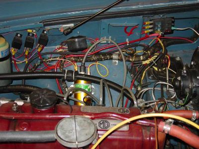
Below, is a photo of my installation of the control head with its vacuum operated cable and the vacuum storage can.
Manifold vacuum is picked up by using a Tee fitting (provided in the kit) below the PCV valve on the intake manifold (HS-4 carbs, 1968 18GF engine). I removed the metal pressed in pipe fitting for the lower PCV valve hose and glued it (using J-B Weld) into the manifold hole. The metal control cable fixing bracket holding the throttle cable is mounted just ahead of it on the same intake manifold utilizing a spare bolt/plug on that manifold. Be sure to seal these threads with some Loctite.
The control unit is mounted via threaded captive nuts installed similarly to "pop rivets". The Blue wire is routed across the back of the top of the radiator diaphram to the coil negative (-) terminal and the red and purple wires routed across the top of the firewall shelf (ahead of the heater and behind the sheet metal heat deflector). All the other wires are routed to the rear of the dash along the bottom of the gutter which runs along the edge of the fender and below the engine hood. The electronic/vacuum control head's throttle control cable is routed in a long sweeping arc from the unit below the carbs and then up over the rocker arm cover to the fixing bracket on the intake manifold.
The second photo below shows my fortunate location for mounting the metal bracket for holding the mechanical control cable in position to properly pull the throttle linkage when in use.
The third photo below shows my choice of control switch location, replacing an unused dual braking system test switch on the upper left corner of the dash.
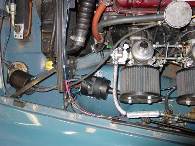 Basic installation of the CCS-100 control head, vacuum canister, and cable mounting bracket in engine compartment. {Yes, that is a cover over the oil cooler for winter driving! Photos taken Fall '06} Basic installation of the CCS-100 control head, vacuum canister, and cable mounting bracket in engine compartment. {Yes, that is a cover over the oil cooler for winter driving! Photos taken Fall '06}
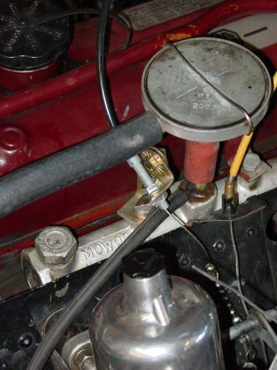 A shot of the linkage mountings and hookup. Not all MGBs may have such an easy time anchoring the linkage mount if their intake manifold does not have these extra available bolts/plugs on it. Some folks may have to fabricate other solutions. A shot of the linkage mountings and hookup. Not all MGBs may have such an easy time anchoring the linkage mount if their intake manifold does not have these extra available bolts/plugs on it. Some folks may have to fabricate other solutions.
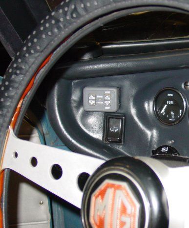 The Audovox CCS-100 Dash control switch mounting I chose. The switch is mounted to a small plastic panel cut to the same size as the dual brake test switch's outside surround so that it would fit as flush as possible. If you can live without the test switch, this is good spot. The idiot light for the dual brake system could be replaced with a 12VDC LED mounted either on the dash or on the center console panel to retain the Alert function from the dual brake system pressure differential switch. The Audovox CCS-100 Dash control switch mounting I chose. The switch is mounted to a small plastic panel cut to the same size as the dual brake test switch's outside surround so that it would fit as flush as possible. If you can live without the test switch, this is good spot. The idiot light for the dual brake system could be replaced with a 12VDC LED mounted either on the dash or on the center console panel to retain the Alert function from the dual brake system pressure differential switch.

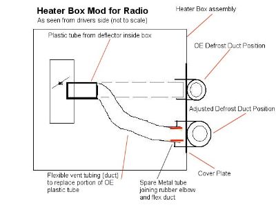 Sorry if this image is too small. Sorry if this image is too small.
Basically, it is my crude drawing to show how I lowered the defroster outlets so that I could accomodate a modern CD player/Tuner and still have the face plate come out flush with the console it is mounted in. If you need a better picture, send me an email.
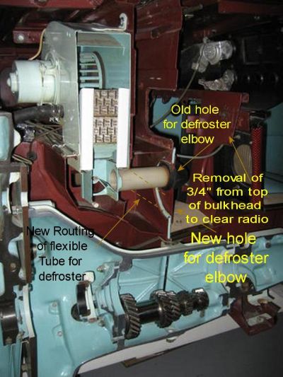 Hopefully you can see the lines and arrows that I hope explain what I did. This is a cross sectional view of the heater box as seen on the full cutaway MGB GT at the British Motor Heritage Museum. Pretty useful photos! This was an early GT (as you can tell by the speaker console) and on the later cars the bulk head opening remained the same, even tho the radio was positioned lower than in these cars. That is why I had to open up the hole in the bulkhead as it simply was in the way of a newer, deeper bodied car stereo. Hopefully you can see the lines and arrows that I hope explain what I did. This is a cross sectional view of the heater box as seen on the full cutaway MGB GT at the British Motor Heritage Museum. Pretty useful photos! This was an early GT (as you can tell by the speaker console) and on the later cars the bulk head opening remained the same, even tho the radio was positioned lower than in these cars. That is why I had to open up the hole in the bulkhead as it simply was in the way of a newer, deeper bodied car stereo.

The MGB never came with relays for the headlamps, choosing to run all lamp current through the main harness and the interior control switches (main dash-mounted lamp switch and the dimmer switches ~ floor and column stalk units). This is adequate, but frankly, not as desirable as using relays to lower the current passing through the harness and these sometimes delicate switches. The main dash switch and the column stalk switches (particularly our recent crop of replacements) will have much increased longevity if the much smaller current necessary to energize a relay passes through them, rather than the rather higher current demands of modern halogen lamps.
I will not attempt to tell you how to do this, but rather recommend a site, a book and a supplier who are much better versed in these matters than I am.
 The front two relays at the far left each control the
high beam and low beam filaments, respectively. The third controls current to the electric cooling fan for the radiator. The front two relays at the far left each control the
high beam and low beam filaments, respectively. The third controls current to the electric cooling fan for the radiator.
In my case one relay controls both
high beam filaments, and the other controls both low beam filaments.
Each relay's main power line from the battery is fused at the fuse
panel in the upper right corner of the compartment. Power wires are
heavy rope-lay high strand count red cabling as used for powering super
high power car stereos. It is very flexible, heavily insulated, and
has excellent conductivity.

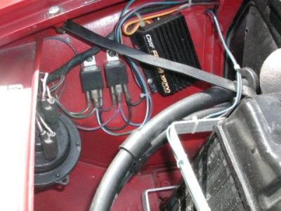 This is Clifton Gordon's relay setup. Note that his are located forward of the radiator diaphram. It is similar to my own and this is another possible choice of location for the relays. These are single pole, single throw relays such as are commonly available over the counter at most Automotive supply stores. This is Clifton Gordon's relay setup. Note that his are located forward of the radiator diaphram. It is similar to my own and this is another possible choice of location for the relays. These are single pole, single throw relays such as are commonly available over the counter at most Automotive supply stores.
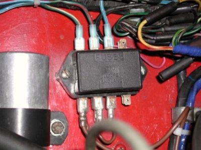 Here you see Clifton's choice of fuse box for his headlamp relays, certainly more British than my choice and enclosed to help keep the fuse contacts clean. Note also that he has used slip on vinyl boots to help protect his wiring terminals. Here you see Clifton's choice of fuse box for his headlamp relays, certainly more British than my choice and enclosed to help keep the fuse contacts clean. Note also that he has used slip on vinyl boots to help protect his wiring terminals.
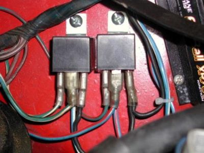 Finally, a close up of Clifton's relays, showing the use of vinyl boots to protect the terminals, and the relays' mounting to the inner fender, via metal (sometimes plastic), mounting tabs integral to the relays. Finally, a close up of Clifton's relays, showing the use of vinyl boots to protect the terminals, and the relays' mounting to the inner fender, via metal (sometimes plastic), mounting tabs integral to the relays.

Dan Masters has established a company, Advance Auto Wire,
http://www.advanceautowire.com/ ,
which offers superbly designed components to complete installation of Headlamp
and other relays to your MGB (and other British cars) and it is well worth your
taking the time to investigate what he offers. They could make your
installation/usage much easier and you would have the assurance that you have
an installation and components offering ultimate and safe integration with your
existing wiring system designed and offered by an acknowledged expert and MGB
enthusiast.
Rick Astley has written a very comprehensive book, "MGB
Electrical Systems, The Essential Manual", published 2006. It is
available from many sources including Little British Car Co., http://www.lbcarco.com/ This
book covers relay usage and installation specifically for the MGB and is a
valuable addition to any owner's library of reference materials for maintenance
and enhancement of their MGB experience.
Fusing of Headlamp Relay Circuits:
An excellent article which points out the benefits of using one fuse per lamp filament, for a total of 4, is to be found at the British V8 site: http://www.britishv8.org/Articles/Headlamp-Circuit-Protection.htm

If you choose to use crimp-on spade terminals as I did, do yourself a favor and get a genuine honest-to-god pro quality crimping tool !!! The cheapo tools at most Auto stores are at best just OK. A purpose-made crimping tool will properly distort (upset) the metal terminal and the wire for a truly secure and electrically sound connection. You should be aware, however, that crimping tools are made in many different styles to properly form crimped connections with the specific terminal types they were designed for. Automotive style connectors used by manufacturers are quite different in design from those designed for use with insulated terminals. Insulated terminals are probably the most readily available to most of us and although they are not always preferable, if used with the correct crimping tool, they can provide reasonable service. A photo of the insulated terminal crimping tool I use is shown below, and you can figure it will cost you about $50+ from an electrical/electronics supplier. Dan Masters discusses using true automotive type crimping tools at his site (again, use link above), in the "Instructions PDF" you will find there.
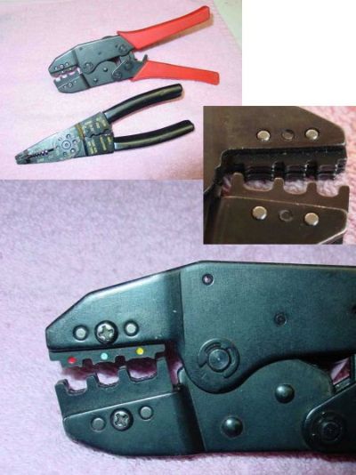 The two tools shown upper left contrast a purpose-built crimping tool for insulated terminals, and one made for general purpose or uninsulated terminals. The shape of the jaws, the pattern of compression, and the much stronger crush of the upper tool make for a much better connection between wire and terminal. The two tools shown upper left contrast a purpose-built crimping tool for insulated terminals, and one made for general purpose or uninsulated terminals. The shape of the jaws, the pattern of compression, and the much stronger crush of the upper tool make for a much better connection between wire and terminal.
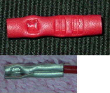 These two photos show a typical insulated crimp connector after being deformed by each of the tools above, both externally and internally. The "crush" on the right is from the purpose-built tool and the results on the left of this connector are the results of the general purpose tool. When the insulating jacket is removed and the actual connector deformation revealed, as you can see, the purpose built tool makes not only a double crush, but also a much more complete connection. The general pupose tool can make an OK connection, but as you see here, the crush was not even and would have only grabbed the wire on one side. In use, this type tool produces hit and miss results. Notice that the cheaper tool even pierces the insulation and exposes the inner connector! Not a very promising result. Just think what the results would have looked like if a simple pair of pliers had been used! These two photos show a typical insulated crimp connector after being deformed by each of the tools above, both externally and internally. The "crush" on the right is from the purpose-built tool and the results on the left of this connector are the results of the general purpose tool. When the insulating jacket is removed and the actual connector deformation revealed, as you can see, the purpose built tool makes not only a double crush, but also a much more complete connection. The general pupose tool can make an OK connection, but as you see here, the crush was not even and would have only grabbed the wire on one side. In use, this type tool produces hit and miss results. Notice that the cheaper tool even pierces the insulation and exposes the inner connector! Not a very promising result. Just think what the results would have looked like if a simple pair of pliers had been used!

Soldering your terminals can make the most reliable connections, but the caution here is to create well-made solder joints.
First, use ONLY Rosin Core solder for electrical work. Never use acid core solder as it will ultimately corrode your electrical connection more than weathering.
Also, make sure that your wire and terminals are CLEAN. All oxidation must be removed, and, if necessary, you may need to trim back the wire past corrosion or oxidation which may have taken place from years of exposure. You can use a small wire brush or wire wheel (as used on a small hand tool like the Dremel Mototool) or even fine garnet sandpaper (do not use carborundum paper) to clean terminal surfaces.
For most soldering on our cars a dual heat Weller soldering gun (about $25 at home improvement stores) is more than adequate to properly heat up almost all of our wiring connections. And know that heat is your friend when making these connections. You must get all the metal components HOT enough to not only melt the solder initially (Temp) when fed off the solder spool, but they must retain enough heat (calories) to melt the solder into a liquid state so that it will flow all around and over all the metal bits that make the connection.
Then, the hot and flowed solder needs to set up with a nice shiny surface.
Cold solder joints, characterized by a dull grey, rough, balled-up look to the solder itself once cooled, are crappy joints and need to be reheated until the solder flows out like melted butter or may need to be redone. You don't need a lot of solder, just enough to get the results mentioned above. Too often cold joints are made when folks are afraid that they will melt the wire's insulation or when the surfaces are dirty, contaminated, or of an incompatible material which does not allow the solder to flow on it.
Sometimes your wire's insulation will melt and/or pull back. You can sometimes beat this problem by using a "heat sink" to block some of that heat. An easy Heat sink you can use is an alligator clip, clipped to the end of the wire so that its jaws make contact with the bare wire just before it enters the solder terminal. Excess heat from the wire will divert into the metal of the clip and help save your wire's insulation. Alligator clips can be found at most electronics stores and even many Auto parts houses for cheap. Some electronics stores even sell specialized alligator clips made just for this purpose. Regardless of which you choose, it will be a tool you can use for a lifetime.
Or, you can reinsulate the connection by adding some heat shrink plastic insulating tubing over the connectors and about 3/8"~1/2" beyond both the connector end and over the wire's insulation for an even better, more weatherproof wiring job. Normally, you push the heat shrink up over the wire before installing and soldering the terminal, and then slide it down over the finished and cooled soldered/crimped on connection and shrink it to fit with heat from a heat gun or even a hair dryer. Note that there is also self-sealing double wall heat shrink tubing available from industrial and electronics suppliers which not only covers your terminal but will seal it from the elements as well.
|