• The Roadster Factory Recovery Fund - Friends, as you may have heard, The Roadster Factory, a respected British Car Parts business in PA, suffered a total loss in a fire on Christmas Day. Read about it, discuss or ask questions >> HERE. The Triumph Register of America is sponsoring a fund raiser to help TRF get back on their feet. If you can help, vist >> their GoFundMe page.
  • Hey there Guest!
    If you enjoy BCF and find our forum a useful resource, if you appreciate not having ads pop up all over the place and you want to ensure we can stay online - Please consider supporting with an "optional" low-cost annual subscription.
    **Upgrade Now**
    (PS: Subscribers don't see this UGLY banner)
Tips
Tips

TR4/4A Wiring to TR4A Wiper Switch

KVH

Darth Vader
Country flag
Offline
There are five spade connectors on the back of my wiper switch. Two on top, two in the middle and one on the bottom. Can anyone say where the red/light green wire gets connected? It would have to go on the bottom I'd think.

I found this pic on the net, and the wiring is much different than mine was, but I'm not sure mine was correct, since I bought the car only last year and never drove it--instead, I tore it down.

My two wires from the top are shown here attached to the middle prongs. Black and brown/green. The red/light green goes on the bottom, I guess. I could try that set up. Any great ideas or thoughts? Will I fry my harness if I copy this set up?
wiper.jpg
 

TR3driver

Great Pumpkin - R.I.P
Offline
I think the information I have says both the photo and your description are wrong. I can't swear this is all correct, bunch of stuff chained together; but I think it is.

This should be the diagram for the 2 speed wiper switch. It was published for the heater switch used on non-AC Stag; which has a different Stanpart number but cross-references to the same Lucas 34317 as the TR4A two speed wiper switch. (The speed markings are backwards to the TR4A wiper, too.) If you look closely at the photo you supplied (I had to save it and blow it up), you can see the terminal numbers cast into the plastic body.
QX8xZY5.jpg


I believe pin 1 (or pin 7) should get the black wire. Pin 4 should get N/LG (high speed, first position). And pin 8 gets R/LG (slow speed, second position).

The screwy thing about this motor is that both wires have to be grounded for slow speed. Unfortunately, if you ground only the slow speed wire, it can damage the motor. There is a resistance wire inside that can overheat.

However, there should be no risk to the harness.
 
OP
KVH

KVH

Darth Vader
Country flag
Offline
Thanks Randall. I'm trying to figure it all out still. I checked the wiring on my other car. It could be way off, but pin 7 is the R/LG, pin 8 is the N/G, and pin 4 is the ground/black. Can it truly be? I think it works that way in my other car, but I do know that speed 1 is so weak I have to use speed 2, and even that is slow, slow, slow.
 

TR3driver

Great Pumpkin - R.I.P
Offline
Your wiper motor is a model DR3A, right? There are other two speed wiper motors and they are wired differently. For example, TR4 with the two speed option had a model 5BSA, and TR6 uses a 14W.

Your wiring would make position 1 ground R/LG, which is wrong according to the documentation I have. NG (only) should be grounded for high speed. I guess it might run (haven't tried it myself) with only R/LG grounded, but I think would be very weak if it runs at all.

Internally, R/LG is connected to the bottom of the field winding; NG is connected to the bottom of the armature (with both fed by 12v from the ignition circuit). There is a resistor between R/LG and NG (which is wrapped around the field windings, making it look like a secondary winding, but the resistance is the important part).

With only R/LG grounded, the current for the armature has to flow through the resistor when the park switch is open (which is the configuration I said before could cause the resistor to overheat, because it's only designed to carry field current which is much less than armature current).

rbP8fCD.jpg


Try it my way, I think you'll be pleasantly surprised.

PS, I failed to record the author of the document where I found the above drawing. If anyone recognizes it, please let me know and I'll try to offer proper credit in the future.
 
OP
KVH

KVH

Darth Vader
Country flag
Offline
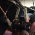
I will take it apart and try again, but I think it failed when I did that. Here's a pic of what I finally wired up, and it worked, though lethargically. Maybe my motor is bad. Will either 1 or 7 work for a ground doing it your way?

switch.jpg
 
OP
KVH

KVH

Darth Vader
Country flag
Offline
I will take it apart and try again, but I think it failed when I did that. Here's a pic of what I finally wired up, and it worked, though lethargically. Maybe my motor is bad. Will either 1 or 7 work for a ground doing it your way?

View attachment 54416
 
OP
KVH

KVH

Darth Vader
Country flag
Offline
I did it again, and what you said worked. Should've known Randall. I used pin 7 for the ground, and I think that made the difference. I have two speeds. Low is very slow. High is slow. But it was '66 I suppose.
 

TR3driver

Great Pumpkin - R.I.P
Offline
Could be other causes. In my case, the rack was very stiff in the tubes. The blades would barely move with the glass dry.
Apparently the tubes had gotten crimped just a bit, in several different places. Probably would have been smarter to just replace them, but I managed to open them up by forcing bearing balls through.
Result is still slow by modern standards, but I don't think they were ever very fast.

Somewhere I've got a spec for how easily the rack should move with the blades lifted from the glass, but I don't have it handy (I'm in Hof's Hut at the moment, trying to escape the heat)
 

TR3driver

Great Pumpkin - R.I.P
Offline
q8TJgAK.jpg
 

JerryVV

Jedi Warrior
Country flag
Offline
If speeds are slow, clean and remove the old grease in the motor gearbox as well as the cable tubes and lightly replace with new grease. A little bit goes a long way and your speeds will be like a new car. Been there done that. Wipers work great now.
 

TexasKnucklehead

Jedi Knight
Country flag
Offline
PS, I failed to record the author of the document where I found the above drawing. If anyone recognizes it, please let me know and I'll try to offer proper credit in the future.

Randall, I think it is from an article here on BCF, I know I found it extremely useful when wiring a TR4a, and then a TR250. There is also some confusion related to the switches as that switch has been used for different seemingly unrelated things. But, I think on the TR250, we took a TR6 headlamp rocker switch, removed the plastic rocker/top part of the switch, and placed into a removed top from bottom of a wiper switch, since the 'guts'/electrical part of one was correct, while the printing on the other was correct and new (TR250 rocker) ones are not available.

Anyway, here's the article where I think your drawing came from. It was well written and very helpful. It was a great marketing idea to make a 2 speed motor -slow and slower.

Home
Member's Articles
The Brain Trust
Lucas DR3A Two-Speed Wiper-motors
by alanjohnturner
Published on 03-02-2013 01:43 PM
 

Scotsman

Jedi Hopeful
Country flag
Offline
I realise this thread is a little old being that it was started in 2018 but I wanted to follow up on it as I had/have the same question as the person who started it (no name given). I tried wiring the switch as per Randall's suggestion (which is the same as that given in the write up in the attached link) with no luck, BUT when wired the way described in the 3rd post of this thread had success (Black to 3/4, Brown/Green to 8, and Red/Green to 7). First stop on switch is fast, second stop (all out) is slow. This is how it the switch was wired originally, but I was having problems because of originally bench testing the wiper motor without using the switch due to it not being in the car when I purchased it. I assumed incorrectly that grounding either Brown/Green, or Red/Green would change speeds.

** I'M CURIOUS TO KNOW IF ANYONE ELSE HAS HAD THIS EXPERIENCE, as the question of how to wire the Lucas DR3A two speed wiper motor appears to be a common one.

My big take home on this is that in order to bench test this motor it is necessary to do it using the switch.

Thanks,

Richard

 
Last edited:

mctriumph

Jedi Warrior
Silver
Country flag
Offline
Nobody has mentioned the wheel boxes. These suffer greatly in the weather and can gradually freeze up .
Remove the wiper arms and use a good penetrating oil (atf & acetone is good) Motors usually last a long time
but too much drag on the system will kill them.
Mad dog
 
Similar threads
Thread starter Title Forum Replies Date
C TR4/4A TR4A 2 speed wiper wiring Triumph 1
N TR4/4A TR4A license plate light wiring Triumph 5
T TR4/4A White wire question on TR4A A-type wiring Triumph 2
T TR4/4A Two quick OD TR4a wiring questions Triumph 7
M TR4/4A TR4A Electric fan wiring ? Triumph 2
T TR4/4A TR4A alternator conversion wiring question Triumph 28
T TR4/4A TR4A wiring - gear reduction & external solenoid? Triumph 6
KVH TR4/4A Stumped on Electrical Wiring--TR4A Triumph 7
J TR4/4A Quick TR4A wiring question Triumph 6
ducatista TR4/4A I need a TR4A wiring diagram Triumph 5
B Land Rover Series 3 Wiring Diagrams Rover / Land Rover 0
J TR2/3/3A Wiring Triumph 11
71TR6 TR2/3/3A A TR3A wiring question Triumph 17
T 1971 Fuse Box and Wiring Triumph 7
tahoe healey Wiring Diagram for Fog Lights Austin Healey 12
P Wanted Wiring scraps Triumph Classifieds 14
olarson TR2/3/3A Horn Replacement Wiring Triumph 7
Sopwith_Camel horn relay wiring Jaguar 3
luke44 TR2/3/3A Calling all Wiring experts TR3 Overdrive Wiring ver A or ver B or are they the same? Triumph 8
K TR2/3/3A Wiring a voltmeter gauge to replace the ammeter. Triumph 1
B Steering Column Wiring/Sealing Austin Healey 1
timsgolf Coil Wiring Austin Healey 20
T Spitfire 67 MK2 Wiring Triumph 12
Joel Lester TR2/3/3A TR3 Wiper motor wiring and testing Triumph 5
P XJ12 Wiring diagrams Jaguar 1
Scotsman Wiring Diagram for 1966 BJ8 Austin Healey 3
J TR6 TR6 Hayden Pusher Fan Wiring Triumph 2
B TR4/4A Basic Wiring Question Triumph 35
C For Sale Center wiring harness for a 1959 Sprite Spridgets Classified 0
I Lotus Elite wiring diagram Lotus 6
K TR2/3/3A British Wiring alternator conversion kit question. Triumph 3
6 BJ8 Headlamp Wiring Austin Healey 1
S MGB mystery wiring plug MG 2
R TR6 Starter wiring question Triumph 6
R Spitfire Turn signal wiring Spitfire Triumph 5
B TR4/4A High Torque Starter Wiring Triumph 9
N For Sale Wiring harness 64-67 mk lll Spridgets Classified 0
J Wiring Harnesses Issues Spridgets 3
S Wiring Harness Replacement Spridgets 1
R Electric fuel pump wiring Spridgets 4
B TR4/4A Wiring Harness Triumph 6
R Wiring ??'s Spridgets 17
Healey Nut Rear Wiring Routing Austin Healey 2
7 General TR Wiring harnesses Triumph 5
Got_All_4 TR5/TR250 Wiring/Electrical Mystery Worked Perfect Then Not Triumph 5
MGTF1250Dave T-Series TF Windscreen Wiper wiring MG 4
M TR6 Fuse box wiring mystery Triumph 9
Healey Nut Wiring Harness Routing Austin Healey 5
J Wiring Harness Austin Healey 5
nichola TR6 Question on new wiring harness Triumph 6

Similar threads

Top