• The Roadster Factory Recovery Fund - Friends, as you may have heard, The Roadster Factory, a respected British Car Parts business in PA, suffered a total loss in a fire on Christmas Day. Read about it, discuss or ask questions >> HERE. The Triumph Register of America is sponsoring a fund raiser to help TRF get back on their feet. If you can help, vist >> their GoFundMe page.
  • Hey there Guest!
    If you enjoy BCF and find our forum a useful resource, if you appreciate not having ads pop up all over the place and you want to ensure we can stay online - Please consider supporting with an "optional" low-cost annual subscription.
    **Upgrade Now**
    (PS: Subscribers don't see this UGLY banner)
Tips
Tips

Headlight relays

mgtf328

Jedi Hopeful
Country flag
Offline
A previous owner fitted halogen headlights, spot lights and a flick switch to flash the headlights operated through relays. I'm no electrician but the wiring needed tidying up so I've been tinkering! I don't have a circuit diagram but I discovered that there are 3 15 amp fuses which come off the 87 relay terminals feeding the hi, dipped and spot lights. There are also two 35amp fuses which I think are the power sources to the relays. I'm not sure what size these fuses should be, 35amp seems a bit high to me and I'm a bit concerned that they seem to be wired in with 15amp connectors, perhaps I should uprate these to 30 amp. Any suggestions on fuse sizes would be greatly appreciated.
Thanks
AJ
 

RAC68

Darth Vader
Offline
Hi AJ,

I have also used 3 relays to control and power my Head and driving lights. Power to the relays is from an alternator using an in-line 20 Amp fuse with each lighting circuit protected by a 10 Amp fuse. With relays, the power passing through the original wiring harness, light switch, and floor high-beam dip switch is greatly reduced to that needed to only switch the relays and not power the lights. This is important as the original incandescent head lights required much less amperage then the newer higher powered Halogens of today and the wiring of the original unfused lighting circuits was lower then I felt safe to depend upon.


Although not knowing how your lighting is wired, I would experiment by reducing the fuse amperage for the circuit supplying operational power for lighting to 15-20 Amps with each lighting circuit to no more then half the main circuit.

Here is a diagram of my installed relay wiring:

Headlight Relays[1].jpg

Enjoy your Healey,
Ray(64BJ8P1)
 

Keoke

Great Pumpkin
Country flag
Offline
First mgtf328:

Get a wiring diagram for your car .

Toms Import Toys:

Is a source noted here on the forum ,

Easter egging around could burn up the whole harness OK


Regarding fuse sizes"

For these type circuits a fast blow fuse with an amperage = to 1 1/2 time the load current should be used.
 

MarkP

Senior Member
Offline
You need to work backwards from the current draw of the light/s. As an example Hella's Plus 7" round halogen headlamp can be spec'd as sealed beam or european ECE with configurable lamp. Standard is 55/65Watt or can be upgraded to 55/100Watt, or whatever is available.

I[SUB](A) = [/SUB]P[SUB](W)[/SUB] / V[SUB](V)[/SUB]

A single 55W lamp will require 4.6 amps
A single 100W lamp will require 8.3 amps

Depending how the headlights and driving lights were spec'd, sum up the current requirement for each leg of the circuit then derate for long term reliability/weakest component (don't forget that the wire itself should be sized appropriately for current and length). As a point of reference Moss Motors headlight relay kit uses a 20a fuse which is marginal for higher performance headlights. Rovers North sells a Performance Headlamp Harness for H4 Style Headlamps that has a 40a fuse, ceramic connectors and larger gauge wire. That harness would work on any vehicle that is planning on upgrading to performance lights.
 
OP
M

mgtf328

Jedi Hopeful
Country flag
Offline
Thanks for the help guys, making some progress now. I have a BJ8 wiring diagramme but this is an add on by a previous owner and all I have is 2 rough sketches which are different. Your diagramme was very helpful Ray. I now understand how it should work. My arrangement is a little different, I have a flick switch to flash the lights and one of the relays is normally closed not open, I think this shuts off the Lo Beam when the lights are flashed. Also I have 4 relays, foot dip switch? I am getting my head around it slowly and have drawn up my own diagramme which I now need to check out on the car when it stops snowing! Not easy as the wiring isn't colour coded! The system works OK and just needs a bit of tidying up but I got a bit concerned that there were two 35A fuses installed in line with what looks like 15A connectors and fuse holders also I would like to know what the 4th relay is for. It looks like I can reduce the 35A fuse to 20/25A the highest load seems to be Hi Beam and Spots together 230watts 19A?. I'll test it out by reducing the fuses 5 amps at a time until they blow. I think LED's are an expensive fix especially as I try to avoid driving in the dark if I can, getting on a bit now!
Thanks again
AJ
 

RAC68

Darth Vader
Offline
Hi AJ,

Sounds like you are on a good path to me. I try to document all my electrical changes so my Son or Grand children can carry on when I'm not able. I have looked at LEDs and have only chosen to use them on my Healey when installing additional brake and turn signals behind my rear red reflectors (incandescent lights heat at the bulb and LEDs heat at the socket). Although LED headlights would reduce amperage passing through your Healey's harness, I see relays as a relatively inexpensive way of eliminating total operational draw (other then relay switching) from this unfused harness.

The foot activated Dip Switch (previously referenced) is the floor switch that switched active headlights between low and high beams.

Please keep us informed.
All the best,
Ray(64BJ8P1)
 

Michael Oritt

Yoda
Gold
Country flag
Offline
Keoke--

What is "Easter Egging around"? I have never heard the term before though I think I get the implication.

Easter egging around could burn up the whole harness OK
 
OP
M

mgtf328

Jedi Hopeful
Country flag
Offline
I wondered what Easter egging was. I decided he meant Easter egg hunting my grandkids get up to in the garden.
Ray, the PO already fitted brake, side and turn signal LED's so your comment set me wondering. I've just braved the cold (it's been snowing here) I took a look at the 4th relay. It has GP written on the side so I'm wondering if it has something to do with the brake light LED's that have green/purple wiring. I'll do some wire chasing when it warms up a bit. I thought LED's required some sort of ballast resister fitted somewhere but I've never noticed one. Perhaps the relay takes it's place.
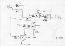
With the help of your diagramme I traced out the attached which I think is how my head/spot lights are wired up. I'll check it out this week. I think R2 is a Normally Closed relay whilst the others are NO. I think this switches the Lo Beam off when the spots and Hi go on and allows the flick switch to work.

Light wiring.jpg

AJ
 

Keoke

Great Pumpkin
Country flag
Offline
OK GuYS:

Easter egging around is a term we use when adequate guidance is not available.

Like no accurate wiring diagrams to follow just huntin N Hopein to find the solution to a problem.----LOL
 

RAC68

Darth Vader
Offline
Hi AJ,

If I am reading your diagram correctly and assuming you have all relays passing power (terminal 30) from the same source (i.e. fused line coming from the alternator or generator), when your Dip Switch is set to HI Beams and you activate the Flip Switch, power is going to your Hi Beams and, if switch is on, Driving Lights from 2 different sources and can not be turned of until you switch the Dip Switch to Low Beams AND turn off the Flick Switch.

Just my thoughts,
Ray(64BJ8P1)
 
OP
M

mgtf328

Jedi Hopeful
Country flag
Offline
Ray, Thanks for your reply. I assume you mean the switch on Terminal 85 R2. It's a spring loaded 'flick' switch on the dash that is normally open unless you hold it down. It flashes the Hi Beam when 'flicked' down even if the dash switch is off, it returns to the off position automatically. R1 is permanently powered even with the dash switch off. To do as you say you'd have to keep it held down or the switch would have to malfunction. As I see it when you flick the switch it energises the Hi Beam and Spots thru R1 and opens R2 so the Lo Beam is shut off. It's only intended for use when the lights are off. You are right, when the dash switch is on and the Dip is on Hi, if you flick the switch then you would power the Hi beam from R3 and R1 but whoever set it up must have assumed you wouldn't flash the headlights when they're switched on and you wouldn't keep you're finger on the flick switch anyway. Having said all that when I've confirmed how all this works I think I will simplifying it all and convert it to your arrangement as I don't like the idea of R1 being permanently energised, the wiring looks a mess and the flick switch could malfunction but I need to figure out what part the 4th relay plays in all this before I think of changing anything.
AJ
 

Keoke

Great Pumpkin
Country flag
Offline
Would LED headlight bulbs use less current and be brighter? Then no relays would need to be added.

Go To:
Super Bright Leds.Com and go to Chat ask your question as Technical and I think you can get accurate technical answers there.
 

steveg

Yoda
Gold
Country flag
Offline
A neighbor has LED headlights on his '57 Porsche Speedster. They provide greatly improved lighting from the 6V system. However, IMO they don't look appropriate. They look kind of like flourescents. YMMV
 

Keoke

Great Pumpkin
Country flag
Offline
Well Steve:

He may not have known the correct brightness and color to order.?

There are a whole lot of LED lamps available as a replacement for one original type bulb
 
OP
M

mgtf328

Jedi Hopeful
Country flag
Offline
It's a moot point but an LED conversion could be illegal in the UK. Cars in the EU need to have European Whole Vehicle Type Approval and you can only use the factory parts (including the automatic levelling using sensors on the suspension, beam spread etc.), or it will not meet the Type Approval. As our cars were built before these Regs were in place I guess this might not apply but the annual road test (known as the MOT over here) tests headlamps and it is possible (likely?) that a conversion to LED's might result in a fail. I for one don't want to go to the expense and find out the car won't pass the test.
AJ
 
OP
M

mgtf328

Jedi Hopeful
Country flag
Offline
Ray, I did get your email thanks a lot and I've downloaded your article. Very interesting. I've been preoccupied with other things and it's been cold here (for us anyway!) and am just getting back to it. I think I have it sorted in my mind now and I am going to tidy it all up. I'm pretty certain that the additional relay is fitted to the side lights as they've been fitted with LED's. I'll disconnect it later today to find out.
AJ
 
Last edited by a moderator:
Similar threads
Thread starter Title Forum Replies Date
Spock TR6 '72 Headlight Relays Triumph 4
4tecdog Headlight relays the easy way Austin Healey 13
B Horn/Headlight Relays Spridgets 13
L BE Headlight Relays- Photos Spridgets 1
Gliderman8 Headlight relays!..... Triumph 24
B Headlight relays Spridgets 2
G Headlight relays Spridgets 11
Hangtown Healey Cibie Z Beam Headlight Repair Austin Healey 0
F TR2/3/3A Headlight bucket color Triumph 22
F TR2/3/3A Headlight bucket clip Triumph 2
Healey Nut Headlight buckets Jaguar 3
B Headlight Dip Switch Austin Healey 4
D TR2/3/3A headlight question Triumph 8
P TR2/3/3A TR2 Headlight Trim Question: Triumph 8
Rob Glasgow Wanted Headlight Lucas Austin Healey Classifieds 4
Bocaray TR2/3/3A Headlight Dimmer conversion to dash switch Triumph 6
RJS General TR Warm White H4 LED Headlight Bulbs Triumph 1
Rob Glasgow For Sale Used headlight rims for sale Austin Healey Classifieds 1
AngliaGT For Sale Lucas Headlight - used MG Classifieds 0
Guido36 LED Headlight Upgrade Austin Healey 1
Healey Nut TR6 Headlight size Triumph 58
D BJ8 Headlight Rims Austin Healey 0
D TR2/3/3A snap on headlight rims restore Triumph 10
steveg TR6 Headlight switch - can it be rebuilt? Triumph 4
dbenichou289 TR2/3/3A Headlight outer trim ring Triumph 6
K TR2/3/3A Headlight Hi beam floor button fail? Triumph 5
dbenichou289 TR2/3/3A headlight switch removal Triumph 10
Upland 3 position headlight switch is now 2 Spridgets 1
AUSMHLY Led headlight conversion kit with Lucas headlight bucket Austin Healey 37
D TR2/3/3A Headlight Trim Triumph 17
P TR6 ^%$#headlight rim Triumph 4
KVH General TR Headlight going out Triumph 9
Rob Glasgow Weird Lucas Headlight Austin Healey 7
D Wanted TR3 Headlight [lamp] chrome rim Triumph Classifieds 1
P TR6 Headlight problem Triumph 3
T TR4/4A Attaching headlight trim ring Triumph 6
S TR4/4A Headlight switch wiring. Please help Triumph 2
GTP1960 TR2/3/3A LED headlight question Triumph 11
K TR4/4A 4A chrome headlight rim installation? Triumph 2
T Question regards headlight ring 'thickness' for bugeye Spridgets 3
S TR2/3/3A Tr3 headlight buckets Triumph 3
healeyblue XK 120 headlight mounting Jaguar 1
Jim_Gruber Headlight Trim Rings on my BE - Removal - Best Methods Spridgets 5
M For Sale E-Type S1 Plexi Headlight Covers Jaguar Classifieds 0
Rut Headlight relay question Spridgets 3
JPSmit Question four - headlight trim ring Spridgets 9
princetn1 MGB Headlight Grille MG 7
TomMull General Tech Headlight upgrade Triumph 9
S Replacement Headlight Switch Spridgets 4
jaegzie Headlight buckets Spridgets 3

Similar threads

Top