• The Roadster Factory Recovery Fund - Friends, as you may have heard, The Roadster Factory, a respected British Car Parts business in PA, suffered a total loss in a fire on Christmas Day. Read about it, discuss or ask questions >> HERE. The Triumph Register of America is sponsoring a fund raiser to help TRF get back on their feet. If you can help, vist >> their GoFundMe page.
  • Hey there Guest!
    If you enjoy BCF and find our forum a useful resource, if you appreciate not having ads pop up all over the place and you want to ensure we can stay online - Please consider supporting with an "optional" low-cost annual subscription.
    **Upgrade Now**
    (PS: Subscribers don't see this UGLY banner)
Tips
Tips

new wiring harness

  • Thread starter Deleted member 21878
  • Start date
D

Deleted member 21878

Guest
Guest
Offline
i have started putting in the new wiring harness. a couple of questions to start:

at the fuse block:
the diagram shows three white wires going to A3. 1) the overdrive relay; 2) the fuel pump; 3) the coil
i have another white wire coming out of the main harness which has continuity to the white wires inside the car.... guessing at this point is the switch since it is a little heavier wire. should that go on the same A3 terminal?

flasher relay:
my cover was off the flasher relay. not sure why. it may have had an issue or it may have just been knocked off. is there a way i can test this unit to make sure it works before i go on?

Thanks
 
OP
D

Deleted member 21878

Guest
Guest
Offline
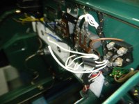
here is a picture of what i am talking about.
the white wire to the bottom goes to the OD relay, the one bent in a "U" goes to the fuel pump, the one bent in a loop goes to the coil.

the other white appears to go to wiring inside the bulkhead. i would assume they all get connected to the same terminal on the fuse block but just wanted to check since the wiring diagram does not show the other white wire.

DSCN0206.jpg
 
Country flag
Offline
The brown wire is for the horns and it gets a 'dedicated' terminal with a 50-amp slow-blow fuse. All the rest go to the other terminal and get a 35-amp slow-blow.
 

RestoreThemAll

Jedi Warrior
Country flag
Offline
Are you adding extra fuses? If not you may want to reconsider. Search the forum. There is plenty of discussion about that.
 
OP
D

Deleted member 21878

Guest
Guest
Offline
i think i figured this one out. on the wiring diagram they show running a white wire out to the coil and then one back to the fuse block. instead of doing that, the harness makers just ran a wire to the fuse block. same result and less wire. makes sense now.

as for adding more fuses, i am going to look in to that as i figure out how the harness is run under the dash. then see what i can come up with. certainly looks like a few in-line fuses are in order at the very least.
 

Rob Glasgow

Jedi Knight
Country flag
Offline
Ditto to Mike Tobin's recommendation of Charlie Hart's fuse block. It's well built, the instructions are spot on and it looks right at home on the car. Plus you've got all the circuits individually protected.
 

RestoreThemAll

Jedi Warrior
Country flag
Offline
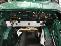
I was also going to suggest Charlie Hart's setup. The one pic is Charlie's setup, more fuses. The other is a schematic that my brother the EE made for me.

I put an in line fuse at the fuel pump and OD switch.
 

Attachments

  • HLY FUSEBLOCK BN1-BJ7 wiring.pdf
    30.3 KB · Views: 130
  • DRAFT Austin-Healey Harness v0 2 with color labels.pdf
    117.7 KB · Views: 110

RAC68

Darth Vader
Offline
Although Charlie Hart's setup is a very good idea to help protect the circuitry and components, I would suggest you consider placing it in a convenient place under the dash and retain the original box to maintain the image of originality. Since you are at a stage in your project to be able to address this much easier then after the completion of your restoration, the implementation of Charlie's box would only require a few hidden wires for the move.

Although my restoration was completed before considering the implementation of a number of additional fuses covering all main circuits, I found it easier to add fuse holders to each of the circuits I wanted to cover. This approach gave me the benefit of being able to focus each fuse on the specific demands of the targeted circuit and/or component with no additional wiring required to get to the specific circuit from a central location. It also allowed me to hide each fuse holder to maintain the original wiring image. However, because of the distribution of protected circuits and the deterioration of my memory with age, I created a directory of protected circuits/components, the location of the fuse, and the size of the fuse. This directory also contained any notes thought advantageous to know for fast access of the fuse and anything helpful or unique that would help quick access and remediation of a related issue.

Just some additional thoughts,
Ray(64BJ8P1)
 
OP
D

Deleted member 21878

Guest
Guest
Offline
Thanks for the info. i would like to keep the original look as close as i can. not that this car is exactly correct but i would like it to look close. printed out both files above and will look in to this.
 
OP
D

Deleted member 21878

Guest
Guest
Offline
i am looking over the Hart set up of the fuse block. they show a white wire to the overdrive switch on the left side of the bar along with the white wire from the switch. then they show the wire to the OD relay on the right as well as the fuel pump.
they do not show the white wire to the coil. was wondering since the white wire to the OD switch comes off the C2 terminal of the relay.... should they really mean the coil wire and not the OD switch?

Thanks
 

Keoke

Great Pumpkin
Country flag
Offline
i have started putting in the new wiring harness. a couple of questions to start:,Whose harness did you BUY!_????
 
OP
D

Deleted member 21878

Guest
Guest
Offline
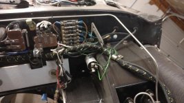
So far mine has been perfect also. i did start pulling my wires for my fuse sub-block. i bought one off of Amazon. should be here Wed. i got an 8 terminal block so i have room for a driving light circuit and have one more just in case. i plan to lay it out just like the Hart set up above.

in stead of pulling out my old fuse block, i am leaving it in. on the left side of the 35amp fuse will be my hot wire from my switch and the wire to the coil. on the right side of that fuse, i ran one green wire headed to the power supply block on the new fuse block. then extended all 5 green wires, the fuel pump wire and the OD relay wire inside. I also ran one red wire from the front of the car for the fog/driving lights. this will go to a switch (not sure where just yet) and then to the fuse block. pic below

on the driving lights, i was considering getting another wiper switch and hopefully a plain knob to put in the dash. Not sure where. looking for ideas on where to install the switch.IMG_0209.jpg
 
Similar threads
Thread starter Title Forum Replies Date
C For Sale Center wiring harness for a 1959 Sprite Spridgets Classified 0
N For Sale Wiring harness 64-67 mk lll Spridgets Classified 0
S Wiring Harness Replacement Spridgets 1
B TR4/4A Wiring Harness Triumph 6
Healey Nut Wiring Harness Routing Austin Healey 5
J Wiring Harness Austin Healey 5
nichola TR6 Question on new wiring harness Triumph 6
R TR2/3/3A Replace wiring harness in steering column Triumph 61
Ripper01 For Sale- TR6 Wiring Harness Triumph Classifieds 0
R TR2/3/3A Install new wiring harness in steering column Triumph 16
ckeithjordan TR2/3/3A Wiring Harness Question[s] Triumph 10
nichola TR6 Victoria British wiring harness for TR6 Triumph 6
C For Sale MGA wiring harness MG Classifieds 3
C MGA Wiring harness question MG 7
BoyRacer Need Tips on getting wiring harness through firewall Austin Healey 4
R TR2/3/3A Installing wiring harness in steering column Triumph 59
BoyRacer How to clean a cloth wiring harness Austin Healey 14
S TR2/3/3A installing the wiring harness Triumph 8
A Spitfire BMCNE -Tech Session Custom Wiring Harness Creation -Links to Album Triumph 2
W TR2/3/3A New wiring harness Triumph 8
T TR2/3/3A Wiring harness Triumph 3
D 62 tri-carb wiring harness Austin Healey 10
Gerald_Gordon TR4/4A Routing of wiring harness to the rear of a 1961 TR4 Triumph 8
SherpaPilot Wiring Harness for XJ6 Jaguar 1
tr3guy TR2/3/3A New Wiring Harness Triumph 7
MisterB How to spin engine sans wiring harness? Austin Healey 3
Rut TR4/4A Wiring harness female bullet connectors Triumph 6
Marvin Gruber BJ8 wiring harness install Austin Healey 6
wkilleffer MGB 1974 MGB- New main wiring harness, but no start MG 11
Rut 73 Midget wiring harness Spridgets 0
K TR2/3/3A Wiring harness "wire gauge" sizes? Triumph 20
G '70 Series II engine bay wiring harness -- Jaguar 7
G '70 Series II engine bay wiring harness -- Jaguar 3
charleyf TR6 Wiring harness/ dash bulbs Triumph 2
K TR2/3/3A Wiring Harness Triumph 9
Got_All_4 TR2/3/3A TR3 A wiring harness Triumph 17
B TR6 Reverse light wiring harness routing Triumph 4
J Protecting new wiring harness under car section-Use clear shrink tubing? Austin Healey 4
mt10flyer TR2/3/3A TR3 wiring harness Triumph 7
Rut Wanted, Bugeye wiring harness Spridgets 0
Griz Rear Wiring Harness Question Austin Healey 6
R TR2/3/3A TR3A Overdrive Wiring Harness Installation Triumph 19
Rut Bugeye wiring harness Spridgets 2
mt10flyer TR2/3/3A Winter Project-Wiring Harness Triumph 4
R New wiring harness Austin Healey 8
MikeAH100M Need New Wiring Harness BN2 Austin Healey 2
P General Tech new wiring harness woes MG 6
D MGB Wiring Harness Installation MG 3
D New custom Bugeye wiring harness Spridgets 39
vette New Wiring Harness Austin Healey 6

Similar threads

Top